D.2 SIMAN and the Run Controller
In a programming language such as Visual Basic or Java, programmers must first define the data types that they will use (int, float, double, etc.) and declare the variables, arrays, classes, etc. for those data types to be used in the program. The programmer then uses flow of control (if-then, while, etc.) statements to use the data types to perform the desired task. Programming in Arena is quite different than programming in a base language like C. An Arena simulation program consists of the flow chart and data modules that have been used or defined within the model. By dragging and dropping flow chart modules and filling in the appropriate dialog box entries you are writing a program. Along with programming comes debugging and making sure that the program is working as it was intended. To be able to better debug your programs, you must have, at the very least, a rudimentary understanding of Arena’s underlying language called SIMAN. SIMAN code is produced by the environment, compiled, and then executed. This section provides an overview of SIMAN and Arena’s debugger called the Run Controller.
D.2.1 SIMAN MOD and EXP Files
To better understand some of the underlying programming concepts within Arena, it is useful to know that Arena is built on top of the SIMAN simulation programming system. To learn more about SIMAN, I suggest reviewing the following two textbooks 1 and Banks et al. (1995).
The section will review the pharmacy model of Chapter 2 in order to provide an overview of SIMAN. You should open up the pharmacy model from Chapter 2 in order to follow along. Using the Run/SIMAN/View menu will generate two files associated with the SIMAN program, the mod (model) file and the exp (experiment) file. The files can be viewed using the Window menu (Figure D.3, within the Arena Environment.
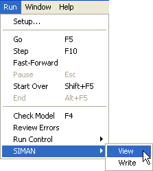
Figure D.3: Run SIMAN view menu
The mod file contains the SIMAN representation for the flow chart modules that were laid out in the model window. The exp file contains the SIMAN representation for the data modules and simulation run control parameters that are used during the execution of the simulation. mod stands for model, and exp stands for experiment.
The following code listing presents the experiment (exp) file for the pharmacy model. For readers that are familiar with C or C++ programming, the exp file is similar to the header files used in those languages. The experiment file defines the elements that are to be used by the model during the execution of the simulation. As indicated for this file, the major elements are categorized as PROJECT, VARIABLES, QUEUES, RESOURCES, PICTURES, REPLICATE, and ENTITIES. Additional categories that are not used (and thus not shown) in this model include TALLIES and OUTPUTS. Each of these constructs will be discussed as you learn more about the modules within the Environment. The experiment module declares and defines that certain elements will be used in the model. For example, the RESOURCES element indicates that there is a resource called Pharmacist that can be used in the model. Understanding the exact syntax of the SIMAN elements is not necessarily important, but being able to look for and interpret these elements can be useful in diagnosing certain errors that occur during the model debugging process. It is important to understand that these elements are defined during the model building process, especially when data modules are filled out within the Environment.
    PROJECT,      "Unnamed Project"," ",,,No,Yes,Yes,Yes,No,No,No,No,No,No;
    VARIABLES:    Get Medicine.WIP,CLEAR(System),CATEGORY("Exclude-Exclude"),DATATYPE(Real):
                  Dispose 1.NumberOut,CLEAR(Statistics),CATEGORY("Exclude"):
                  Create Customers.NumberOut,CLEAR(Statistics),CATEGORY("Exclude"):
                  Get Medicine.NumberIn,CLEAR(Statistics),CATEGORY("Exclude"):
                  Get Medicine.NumberOut,CLEAR(Statistics),CATEGORY("Exclude");
                      QUEUES:       Get Medicine.Queue,FIFO,,AUTOSTATS(Yes,,);
    PICTURES:     Picture.Airplane:
                  Picture.Green Ball:
                  Picture.Blue Page:
                  Picture.Telephone:
                  Picture.Blue Ball:
                  Picture.Yellow Page:
                  Picture.EMail:
                  Picture.Yellow Ball:
                  Picture.Bike:
                  Picture.Report:
                  Picture.Van:
                  Picture.Widgets:
                  Picture.Envelope:
                  Picture.Fax:
                  Picture.Truck:
                  Picture.Person:
                  Picture.Letter:
                  Picture.Box:
                  Picture.Woman:
                  Picture.Package:
                  Picture.Man:
                  Picture.Diskette:
                  Picture.Boat:
                  Picture.Red Page:
                  Picture.Ball:
                  Picture.Green Page:
                  Picture.Red Ball;
    RESOURCES:    Pharmacist,Capacity(1),,,COST(0.0,0.0,0.0),CATEGORY(Resources),,AUTOSTATS(Yes,,);
    REPLICATE,    1,,HoursToBaseTime(10000),Yes,Yes,,,,24,Minutes,No,No,,,Yes;
    ENTITIES:     Customer,Picture.Van,0.0,0.0,0.0,0.0,0.0,0.0,AUTOSTATS(Yes,,);
The following listing presents the contents of the SIMAN model (mod) file for the Pharmacy model. The model file is similar in spirit to the “.c" or”*.cpp" files in C/C++ programming. It represents the flow chart portion of the model. In this code, ";" indicates a comment line. The capitalized commands represent special SIMAN language keywords. For example, the ASSIGN keyword is used to indicate an assignment statement, i.e. variable = expression.
    ;
    ;     Model statements for module:  BasicProcess.Create 1 (Create Customers)
    ;
    2$            CREATE,        1,MinutesToBaseTime(expo(6)),Customer:MinutesToBaseTime(EXPO(6)):NEXT(3$);

    3$            ASSIGN:        Create Customers.NumberOut=Create Customers.NumberOut + 1:NEXT(0$);
    ;
    ;
    ;     Model statements for module:  BasicProcess.Process 1 (Get Medicine)
    ;
    0$            ASSIGN:        Get Medicine.NumberIn=Get Medicine.NumberIn + 1:
                                 Get Medicine.WIP=Get Medicine.WIP+1;
    9$            QUEUE,         Get Medicine.Queue;
    8$            SEIZE,         2,VA:
                                 Pharmacist,1:NEXT(7$);

    7$            DELAY:         expo(3),,VA;
    6$            RELEASE:       Pharmacist,1;
    54$           ASSIGN:        Get Medicine.NumberOut=Get Medicine.NumberOut + 1:
                                 Get Medicine.WIP=Get Medicine.WIP-1:NEXT(1$);
    ;
    ;
    ;     Model statements for module:  BasicProcess.Dispose 1 (Dispose 1)
    ;
    1$            ASSIGN:        Dispose 1.NumberOut=Dispose 1.NumberOut + 1;
    57$           DISPOSE:       Yes;
There are two keywords that you should immediately recognize from the model window, CREATE and DISPOSE. Each non-commented line has a line number that identifies the SIMAN statement. For example, 57$ identifies the DISPOSE statement. These line numbers are especially useful in following the execution of the code. For example, within the code, you should notice the use of the NEXT() keyword. For example, on line number 54$, the keyword NEXT(1$) redirects the flow of control to the line statement 1$. You should also notice that many lines of code are generated from the placement of the three modules (CREATE, PROCESS, DISPOSE). Much of this SIMAN code is added to the model to enable additional statistical collection. The exact syntax associated with this generated SIMAN code will not be the focus of the discussion; however, the ability to review this code and interpret its basic functionality is essential when developing and debugging complex models. The code generated within the experiment and model files is not directly editable. The only way to change this code is to change the model in the data modules or within the model window. Finally, the SIMAN code is not directly executed on the computer. Before running the model, the SIMAN code is checked for syntax or other errors and then is translated to an executable form via a C/C++ compiler translation.
In a programming language like “C", the program starts at a clearly defined starting point, e.g. the”main()" function. Arena has no such main() function. Examining the actual SIMAN code that is generated from the model building process does not yield a specific starting point either. So where does start executing? To fully answer this question involves many aspects of simulation that have not yet been examined. Thus, at this point, a simplified answer to the question will be presented.
A simulation program models the changes in a system at specific events in time. These events are scheduled and executed by the simulation executive ordered by time. starts executing with the first scheduled event and then processes each event sequentially until there are no more events to be executed. Of course, this begs the question, how does the first event get scheduled? In , the first event is determined1 by the CREATE module with the smallest “First Creation" time. Figure D.4 illustrates the dialog box for the CREATE module. The text field labeled”First Creation" accepts an expression that must evaluate to a real number. In the figure, the expo() function is used to generate a random variable from the exponential distribution with a mean of six minutes to be used as the time of the event associated with the creation of an entity from this CREATE module.
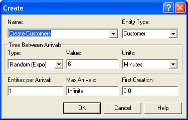
Figure D.4: CREATE module dialog
The careful reader should have the natural question, “What if there are ties?" In other words, what if there are two or more CREATE modules with a”First Creation" time set to the same value. For example, it is quite common to have multiple CREATE modules with their First Creation time set at zero. Which CREATE module will go first? This is where looking at the SIMAN model output is useful. The CREATE module with the smallest First Creation time that is listed first in the SIMAN model file will be the first to execute. Thus, if there are multiple CREATE modules each with a First Creation time set to zero, then the CREATE module that is listed first will create its entity first. Well, this is a simplified discussion. In general,there are other ways to get an initial event scheduled.
Now that we know that there is a language underneath Arena, we can better use Arena’s debugging tool: the Run Controller. The next section provides an overview of using the run controller.
D.2.2 Using the Run Controller
An integral part of any programming effort is debugging the program. Simulation program development in is no different. You have already seen how to do some rudimentary tracing via the READWRITE module; however, this section discusses some of the debugging and tracing capabilities that are built into the Environment. Arena’s debugging and tracing facilities come in two major forms: the run controller and animation. Some of the basic capabilities of Arena’s animation have already been demonstrated. Using animation to assist in checking your model logic is highly recommended. Aspects of animation will be discussed throughout this text; however, in this section concentrates on using Arena’s Run Controller. Arena’s Run Controller is found on the Run menu as shown in Figure D.5.
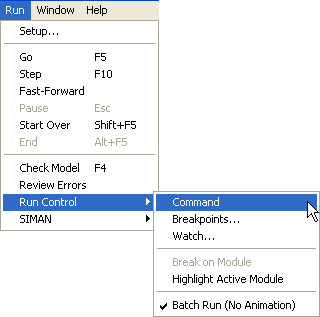
Figure D.5: Invoking the Run Controller
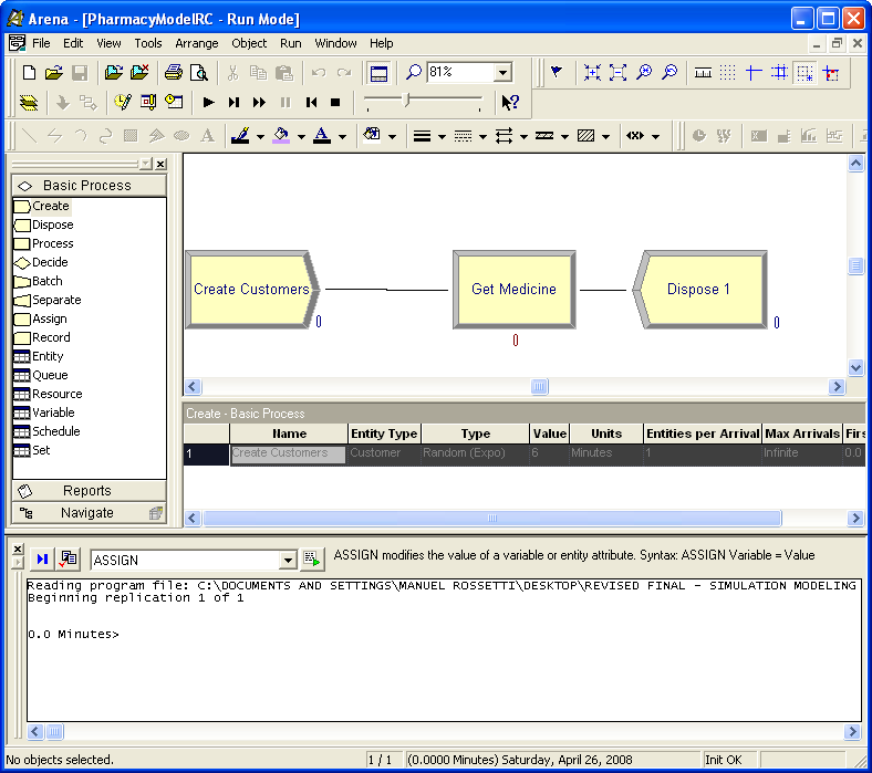
Figure D.6: Arena Environment with Run Controller invoked
Figure D.6 illustrates how the Arena Environment appears after the run controller has been invoked on the original pharmacy model. The run controller allows tracing and debugging actions to be performed by the user through the use of various commands. Let’s first learn about the various commands and capabilities of the run controller. Go to Help and in the index search type in "Command-Driven Run Controller Introduction". You should see a screen that looks something like that shown in Figure D.7.
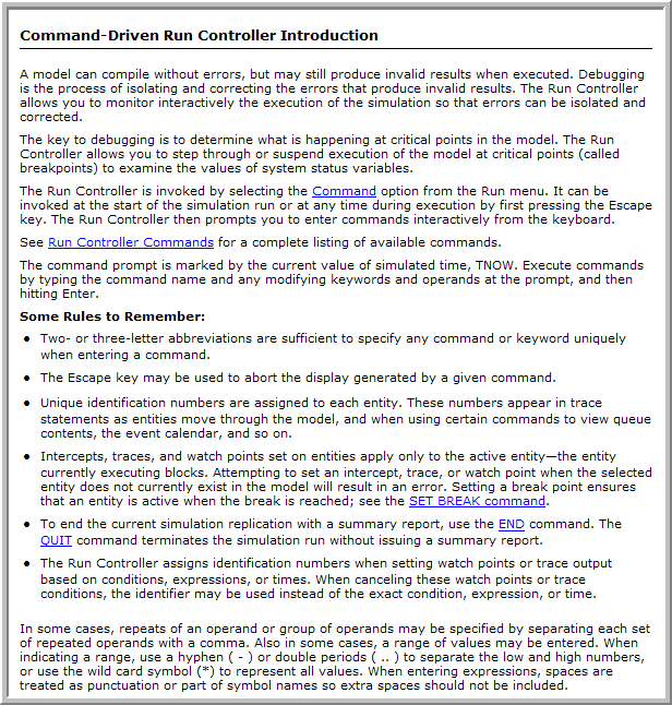
Figure D.7: Getting help for the Run Controller
The Run Controller allows the system to be executed in a debugging mode. With the run controller, you can set trace options, watch variables and attributes, run the model until certain time or conditions are true, examine the values of entities attributes, etc. Within the help system, use the hyperlink that says "Run Controller Commands". You will see a list of commands for the run controller as shown in Figure D.8. Selecting any of these provides detailed instructions on how to use the command within the run controller environment.
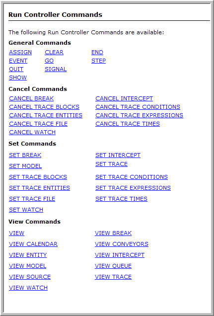
Figure D.8: The Run Controller commands
In what follows, some simple commands will be used to examine the drive through pharmacy model. Open the pharmacy model within and then open up the CREATE module and make sure that the time of the first arrival is set to 0.0. In addition, open up the PROCESS module and make sure that the delay expression is EXPO(5). This will help in ensuring that your output looks like what is shown in the figures. The first arrival will be discussed in what follows.
Now, you should invoke the run controller as indicated in Figure D.5. This will start the run of the model. will immediately pause the execution of the model at the first execution step. You should see a window as illustrated in Figure D.6. Let’s first turn the tracing on for the model. By default, embeds tracing output into the SIMAN code that is generated. Information about the current module and the active entity will be displayed. To turn on the tracing, enter "set trace" at the prompt (in Figure D.9) or select the command from the drop down menu of commands, then press return to enter the command. You can also press the toggle trace button.
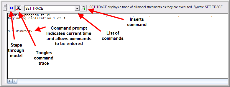
Figure D.9: Using commands in the Run Controller
Now select the ’VCR-like run button for single stepping through the model. The button is indicated in Figure D.10. You should single step again into the model. Your command window should look like Figure D.10. Remember that the CREATE module was set to create a single arrival at time 0.0. This is exactly what is displayed. In addition, the trace output is telling you that the next arrival will be coming at time 2.0769136. The asterisk marking the output indicates the SIMAN statement that will be executed on the next step. Then, when the step executes the trace results are given and the next statement to execute is indicated.
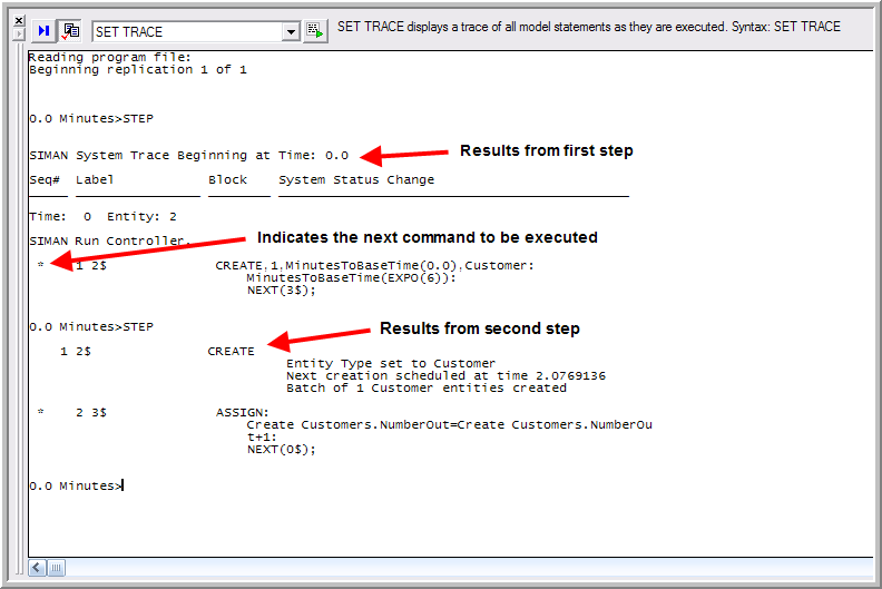
Figure D.10: Run Controller output window after 2 steps
If you press the single step button twice, you will see that ASSIGN statements are executed and that the current entity is about to execute a QUEUE statement. After seven steps, the run controller output should appear as shown in Figure D.11.
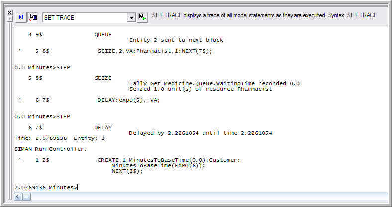
Figure D.11: Run Controller output window after 7 steps
From this trace output, it is apparent that the entity was sent directly to the SEIZE block from the QUEUE block where it seized 1 unit of the pharmacist. Then, the entity proceeded to the DELAY block where it was delayed by 2.2261054 time units. This is the service time of the entity. Since the entity is entering service at time 0.0, it will thus leave at time 2.2261054. In summary, Entity 2 was created at time zero, arrived to the system, and attempted to get a unit of the pharmacist. Since the pharmacist was idle at the start of the simulation, the entity did not have to wait in queue and was able to immediately start service.
Now, something new has happened. The time has jumped to 2.0769136. As
you might recall, this was the time indicated by the CREATE module for
the next entity to arrive. This entity is denoted by the number 3.
Entity 3 is now the active entity. What happened to Entity 2? It was
placed on the future events list by the DELAY module and is scheduled to
“wake up" at time 2.2261054. By using the VIEW CALENDAR command, you
can see all the events that are scheduled on the event calendar.
Figure D.12 illustrates the output of the VIEW CALENDAR
command. There are two data structures within to hold entities that are
scheduled. The”current events chain" represents the entities that are
scheduled to occur at the current time. The "future events heap"
represents those entities that are scheduled in the future.
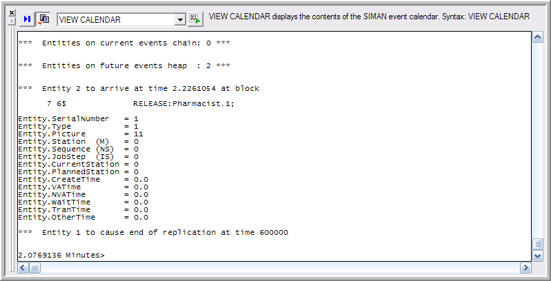
Figure D.12: VIEW CALENDAR output
This output indicates that no other entities are scheduled for the
current time and that Entity 2 is scheduled to activate at time
2.2261054. The entity is not going to ’arrive" as indicated. This is a
typo in the output. The actual word should be "activate". In addition,
the calendar indicates that an entity numbered 1 is scheduled to cause
the end of the simulation at time 600000.0. uses an internal entity to
schedule the event that represents the end of a replication. If there
are a large number of entities on the calendar, then the VIEW CALENDAR
command can be very verbose.
Single stepping the model allows the next entity to be created and arrive to the model. This was foretold in the last trace of the CREATE module.
The run controller provides the ability to stop the execution when a
condition occurs. Suppose that you are interested in examining the
attributes of the customers in the queue when at least 2 are waiting.
You can set a watch on the number of customers in the queue and this
will cause to stop whenever this condition becomes true. Then, by using
the VIEW QUEUE command you can view the contents of the customer waiting
queue. Carefully type in SET WATCH NQ(Get Medicine.Queue) = = 2 at the
run controller prompt and hit return. Your run controller should look
like Figure D.13.
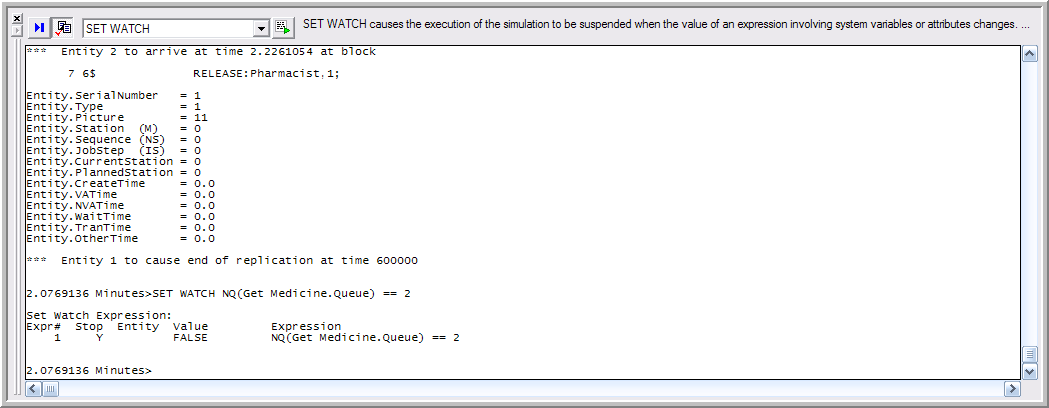
Figure D.13: Setting a WATCH on a variable
If you type GO at the run controller prompt, will run until the watch
condition is met, see Figure D.14. The VIEW QUEUE command will show all
the entities in all the queues, see Figure D.15. You can also select only certain queues and
only certain entities. See the Arena’s help for how to specialize the
commands.
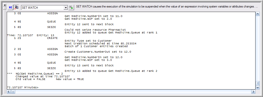
Figure D.14: Output after WATCH condition break
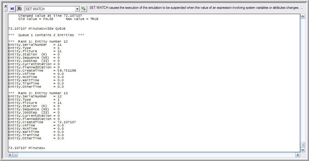
Figure D.15: Output after VIEW QUEUE
Arena also has a debugging bar within the run command controller that can be accessed from the Run \(>\) Run Control \(>\) Breakpoints menu, see Figure D.6. This allows the user to easily set breakpoints, view the calendar, view the attributes of the active entity, and set watches on the model. The debug bar is illustrated for this execution after the next step in Figure D.16. In the figure, the active entity tab is open to allow the attributes of the entity to be seen. The functionality of the debug bar is similar to many debuggers. The help system has a discussion on how to use the tabs within the debug bar. You can find out more by searching for Debug Bar in Arena’s help system.
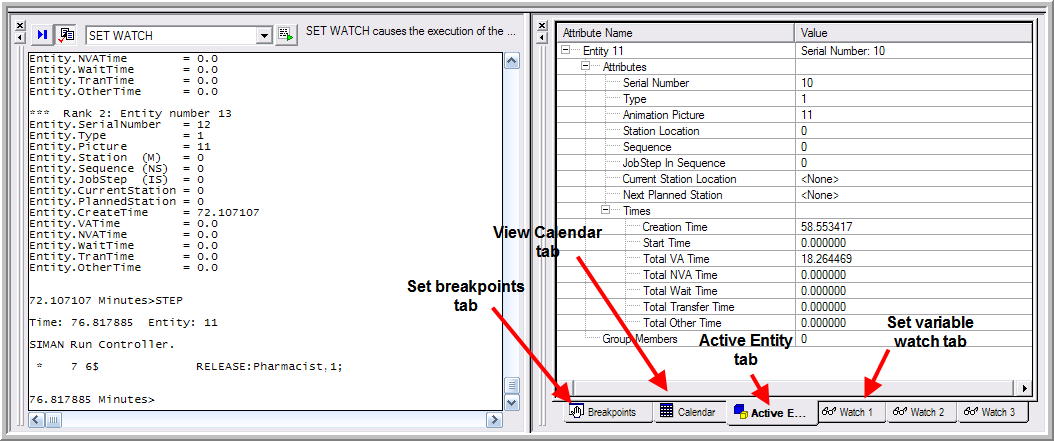
Figure D.16: Debug window within the Run Controller
There are many commands that you can try to use during your debugging. Only a few commands have been discussed here. What do you think the following commands do?
go until 10.0show NR()show NQ()view entity
Restart your model. Turn on the tracing, type them in, and find out!
There are just a couple of final notes to mention about using the Run Controller. When the model runs to completion or if you stop it during the run, the run controller window will show the text based statistical results for your model, which can be quite useful. In addition, after you are done tracing your model, be sure to turn the tracing off (CANCEL TRACE) and to save the model with the tracing off. After you turn the tracing on for a model, Arena remembers this even though you might not be running the model via the run controller. The trace output will still be produced and will significantly slow the execution of your model down. In addition, the memory requirements of the trace output can be quite large and you may get out of memory errors for what appears to be inexplicable reasons. Don’t forget to turn the tracing off and to re-save!
The following section introduces some additional programming concepts that may prove useful when building Arena models.