8.3 Answering the Basic Modeling Questions
From your reading of the contest problem, you should have some initial ideas for how to approach this modeling effort. The following sections will walk through the simulation modeling steps in order to develop a detailed solution to the contest problem. As you proceed through the sections, you might want to jot down your own ideas and attempt some of your own analysis. While your approach may be different than what is presented here, your effort and engagement in the problem will be important to how much you get out of this process. Let’s begin the modeling effort with a quick iteration through the basic modeling questions.
\(\blacksquare\) What is the system? What information is known by the
system?
The purpose of the system is to process test samples within test cells
carried by sample holders on a conveyor. The system is well described by
the contest problem. Thus, there is no need to repeat the system
description here. In summary, the information known by the system is as
follows:
Conveyor speed, total length, and spacing around the conveyor of entry and exit points for the test cells and the load/unload area
Load/Unload machine cycle time, TRIA(0.18, 0.23, 0.45) minutes
Manual preparation time
Cycle times for each tester. See Table 8.4.
Time to failure and repair distributions for testers 1, 3-5. See Table 8.5.
Test 2 usage count to cleaning and cleaning time distribution, TRIA(5.0, 6.0, 10.0) minutes
Sample arrival mean arrival rate by hour of the day. See Table 8.6.
Nine different test sequences for the samples along with the probability associated with each sequence.
A distribution governing the probability of rush samples within the system and a criteria for rush samples to meet (30 minute testing time).
Equipment costs for testers and sample holders. In addition, the cost of implementing additional logic within the model.
From this initial review of the information and the contest problem description, you should be able to develop an initial list of the modeling constructs that may be required in the model.
The initial list should concentrate on identifying primarily data modules. This will help in organizing the data related to the problem. From the list, you can begin to plan (even at this initial modeling stage) on making the model more data driven. That is, by thinking about the input parameters in a more general sense (e.g. expressions and variables), you can build the model in a manner that can improve its usability during experimentation. Based on the current information, a basic list of modeling constructs might contain the following:
CONVEYOR and SEGMENT Modules: To model the conveyor.
STATION Modules: To model the entry and exit points on the conveyor for the testers and the load/unload cell.
SEQUENCE Module: To model the test sequences for the samples.
EXPRESSION Module: To hold the load/unload cycle time and for an array of the cycle times for each tester. Can also be used to hold an expression for the manual preparation time, the sequence probability distribution and the rush sample distribution.
FAILURE Modules: To model both count based (for Tester 2) and time based failures.
ARRIVAL Schedule Module: To model the non-stationary arrival pattern for the samples.
VARIABLE Module: To include various system wide information such as cost information, number of sample holders, load/unload machine buffer capacity, test cell buffer capacity, test result criteria, etc.
Once you have some organized thoughts about the data associated with the problem, you can proceed with the identification of the performance measures that will be the major focus of the modeling effort.
\(\blacksquare\) What are the required performance measures?
From the contest problem description, the monthly cost of the system
should be considered a performance measure for the system. The cost of
the system will certainly affect the operational performance of the
system. In terms of meeting the customer’s expectations, it appears that
the system time for a sample is important. In addition, the contract
specifies that test results need to be available within 60 minutes for
regular samples and within 30 minutes for rush samples. While late
reports do not have to be prevented, they should be rare. Thus, the
major performance measures are:
Monthly cost
Average system time
Probability of meeting contract system time criteria
In addition to these primary performance measures, it would be useful to keep track of resource utilization, queue times, size of queues, etc., all of which are natural outputs of a typical model.
\(\blacksquare\) What are the entities? What information must be
recorded or remembered for each entity? How should the entities be
introduced into the system?
Going back to the definition of an entity (An object of interest in the
system whose movement or operation within the system may cause the
occurrence of events), there appear to be two natural candidates for
entities within the model:
Samples – Arrive according to a pattern and travel through the system
Sample holders – Move through the system (e.g. on the conveyor)
To further solidify your understanding of these candidate entities, you should consider their possible attributes. If attributes can be identified, then this should give confidence that these are entities. From the problem, every sample must have a priority (rush or not), an arrival time (to compute total system time), and a sequence. Thus, priority, arrival time, and sequence appear to be natural attributes for a sample. Since a sample holder needs to know whether or not it has a sample, an attribute should be considered to keep track of this for each sample holder. Because both samples and sample holders have clear attributes, there is no reason to drop them from the list of candidate entities.
Thinking about how the candidate entities can enter the model will also assist in helping to understand their modeling. Since the samples arrive according to a non-stationary arrival process (with mean rates that vary by hour of the day), the use of a CREATE module with an ARRIVAL schedule appears to be appropriate. The introduction of sample holders is more problematic. Sample holders do not arrive to the system. They are just in the system when it starts operating. Thus, it is not immediately clear how to introduce the sample holders. Ask yourself, how can a CREATE module be used to introduce sample holders so that they are always in the system? If all the sample holders arrive at time 0.0, then they will be available when the system starts up. Thus, a CREATE module can be used to create sample holders.
At this point in the modeling effort, a first iteration on entity modeling has been accomplished; however, it is important to understand that this is just a first attempt at modeling and to remember to be open to future revisions. As you go through the rest of the modeling effort, you should be prepared to revise your current conceptual model as deeper understanding is obtained.
To build on the entity modeling, it is natural to ask what resources are used by the entities. This is the next modeling question.
\(\blacksquare\) What are the resources that are used by the entities?
Which entities use which resources and how?
It is useful to reconsider the definition of a resource:
- Resource A limited quantity of items that are used (e.g. seized and released) by entities as they proceed through the system. A resource has a capacity that governs the total quantity of items that may be available. All the items in the resource are homogeneous, meaning that they are indistinguishable. If an entity attempts to use a resource that does not have units available it must wait in a queue.
Thus, the natural place to look for resources is where a queue of entities may form. Sample holders (with a sample) wait for testers. In addition sample holders, with or without a sample, wait for the load/unload machine. Thus, the testers and the load/unload machine are natural candidates for resources within the model. In addition, the problem states that:
Samples arriving at the laboratory initially undergo a manual preparation for the automated system. The sample is then placed in the input queue to the load/unload area. This manual preparation typically requires about 5 minutes. When the sample reaches the front of the queue, it waits until an empty sample holder is available.
It certainly appears from this wording that the availability of sample holders can constrain the movement of samples within the model. Thus, sample holders are a candidate for resource modeling.
A couple of remarks about this sort of modeling are probably in order. First, it should be more evident from the things identified as waiting in the queues that samples and sample holders are even more likely to be entities. For example, sample holders wait in queue to get on the conveyor. Now, since sample holders wait to get on a conveyor, does that mean that the conveyor is a candidate resource? Absolutely, yes! In this modeling, you are identifying resources with a little “r.” You are not identifying RESOURCES (a.k.a. things to put in the RESOURCE module)! Be aware that there are many ways to model resources within a simulation (e.g. inventory as a resource with WAIT/SIGNAL). The RESOURCE module is just one very specific method. Just because you identify something as a potential resource, it does not mean you have to use the RESOURCE module to model how it constrains the flow of entities.
The next step in modeling is to try to better understand the flow of entities by attempting to give a process description.
\(\blacksquare\) What are the process flows? Sketch the process or make
an activity flow diagram
The first thing to remember when addressing process flow modeling is
that you are building a conceptual model for the process flow. As you
should recall, one way to do this is to consider an activity diagram (or
some sort of augmented flow chart). Although in many of the previous
modeling examples, there was almost a direct mapping from the conceptual
model to the model, you should not expect this to occur for every
modeling situation. In fact, you should try to build up your conceptual
understanding independent of the modeling language. In addition, the
level of detail included in the conceptual modeling is entirely up to
you! Thus, if you do not know how to model a particular detail then you
can just "black box it" or just omit it to be handled later.
Suppose an entity goes into an area for which a lot of detail is required. Just put a box on your diagram and indicate in a general manner what should happen in the box. If necessary, you can come back to it later. If you have complex decision logic that would really clutter up the diagram, then omit it in favor of first understanding the big picture. The complicated control logic for sample holders accessing the load/unload device and being combined with samples is an excellent candidate for this technique.
Before proceeding you might want to try to sketch out activity diagrams for the samples and the sample holders. Figure 8.15 presents a simplified activity diagram for the samples. They are created, go through a manual preparation activity, and then flow into the input queue. Whether they wait in the input queue depends upon the availability of the sample holder. Once they have a sample holder, they proceed through the system. The sample must have a sample holder to move through the system. Figure 8.16 illustrates a high level activity cycle diagram for the sample holders. Based on a sequence, they convey (with the sample) to the next appropriate tester. After each test is completed, the sample and holder are conveyed to the next tester in the sequence until they have completed the sequence. At that time, the sample holder and sample are conveyed to the load/unload machine where they experience the load/unload cycle time once they have the load/unload machine. If a sample is not available, the sample holder is conveyed back to the load/unload area.
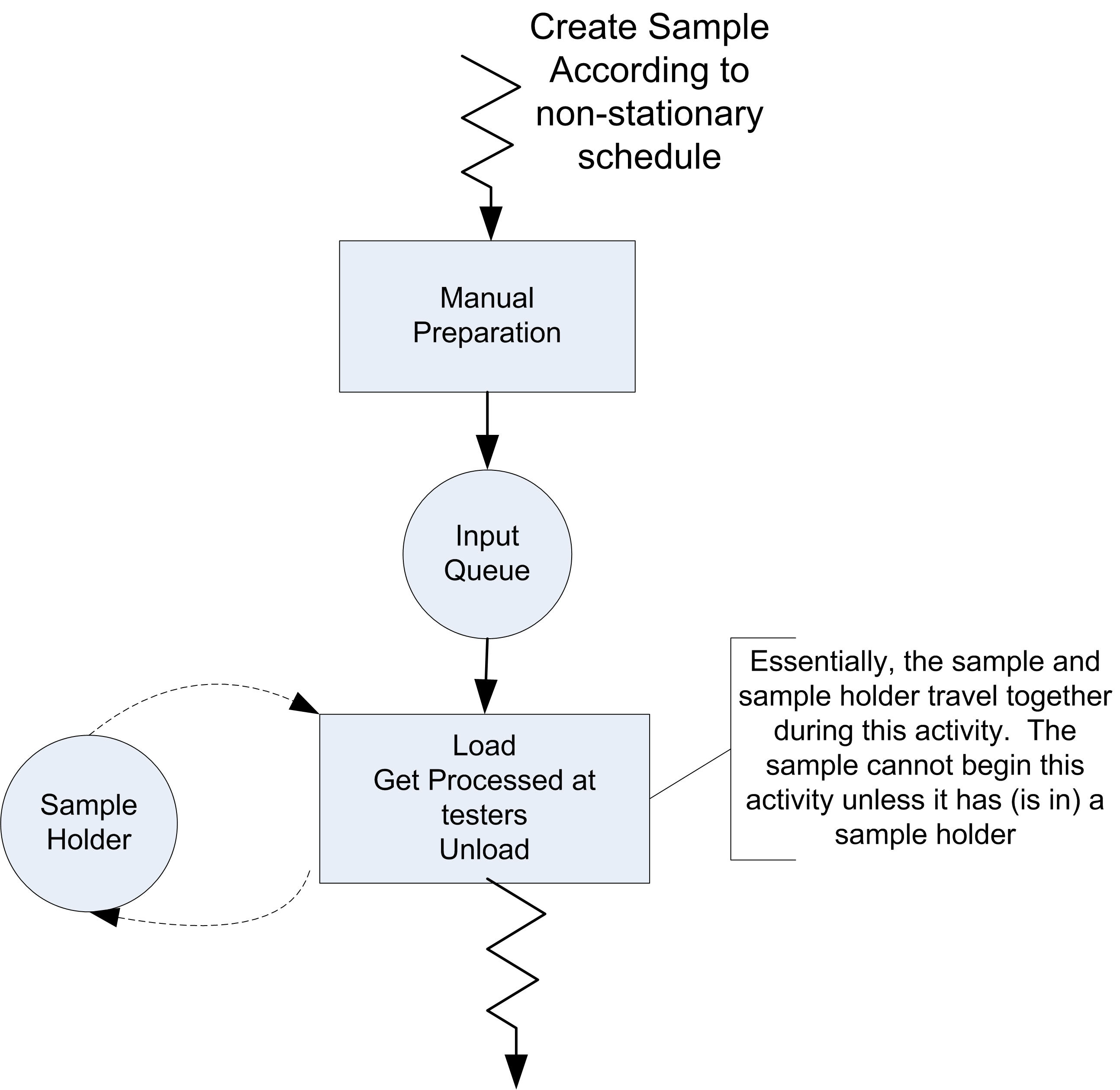
Figure 8.15: Activity diagram for samples process
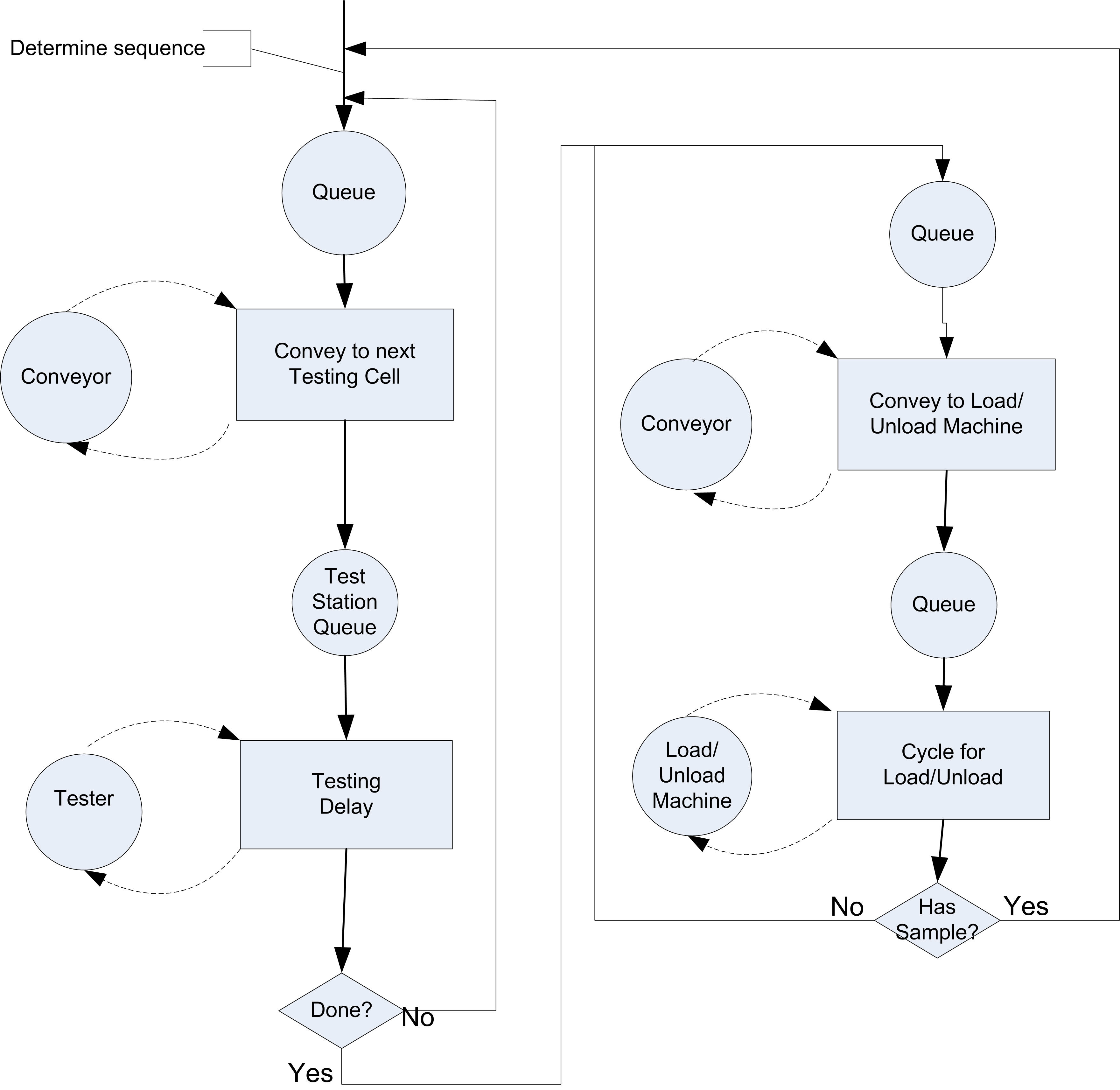
Figure 8.16: Activity cycle diagram for sample holders
One thing to notice from this diagram is that the sequence does not have to be determined until the sample and holder are being conveyed to the first appropriate test cell. Also, it is apparent from the diagram that the load/unload machine is the final location visited by the sample and sample holder. Thus, the enter load/unload station can be used as the last location when using the SEQUENCE module. This diagram does not contain the extra logic for testing if the queue in front of a tester is full and the logic associated with the buffer at the load/unload machine.