7.3 Modeling Systems with Conveyors
A conveyor is a track, belt, or some other device that provides movement over a fixed path. Typically, conveyors are used to transport items that have high volumes over short to medium range distances. The speeds of conveyance typically range from 20-80 feet per minute to as fast as 500 feet per minute. Conveyors can be gravity based or powered. The modeling of conveyors can be roughly classified as follows:
- Accumulating
Items on the conveyor continue to move forward when there is a blockage on the conveyor.
- Non-accumulating
Items on the conveyor stop when the conveyor stops
- Fixed spacing
Items on the conveyor have a fixed space between them or the items ride in a bucket or bin.
- Random spacing
Items are placed on the conveyor in no particular position and take up space on the conveyor.
You have experienced conveyors in some form. For example, the belt conveyor at a grocery store is like an accumulating conveyor. An escalator is like a fixed spaced non-accumulating conveyor (the steps are like a bucket for the person to ride in. People movers in airports are like non-accumulating, random spacing conveyors. When designing systems with conveyors there are a number of performance measures to consider:
- Throughput capacity
The number of loads processed per time
- Delivery time
The time taken to move the item from origin to destination
- Queue lengths
The queues to get on the conveyor and for blockages when the conveyor accumulates
- Number of carriers used or the space utilized
The number of spaces on the conveyor used
The modeling of conveyors does not necessarily require specialized simulation constructs. For example, gravity based conveyors can be modeled as a PROCESS or a DELAY with a deterministic delay. The delay is set to model the time that it takes the entity to fall or slide from one location to another. One simple way to model multiple items moving on a conveyor is to use a resource to model the front of the conveyor with a small delay to load the entity on the conveyor. This allows for spacing between the items on the conveyor. Once on the conveyor the entity releases the front of the conveyor and delays for its move time to the end of the conveyor. At the end of the conveyor, there could be another resource and a delay to unload the conveyor. As long as the delays are deterministic, the entities will not pass each other on the conveyor. If you are not interested in modeling the space taken by the conveyor, then this type of modeling is very reasonable. (Henriksen and Schriber 1986) discuss a number of ways to approach the simulation modeling of conveyors. When space becomes an important element of the modeling, then the simulation language constructs for conveyors become useful. For example, if there actually is a conveyor between two stations and the space allocated for the length of the conveyor is important to the system operation, you might want to use conveyor related modules.
In , a conveyor is a material-handling device for transferring or moving entities along a pre-determined path having fixed pre-defined loading and discharge points. Each entity to be conveyed must wait for sufficient space on the conveyor before it can gain entry and begin its transfer. In essence, simulation modeling constructs for conveyors model the travel path via a mapping of space/distance to resources. Space along the path is divided up into units of resources called cells. The conveyor is then essentially a set of moving cells of equal length. Whenever an entity reaches a conveyor entry point it must wait for a predefined amount of unoccupied and available consecutive cells in order to get on the conveyor.
Figure 7.23 illustrates the idea of modeling a conveyor as a set of contiguous cells representing the space on the conveyor. One way to think of this is like an escalator with each cell being a step.
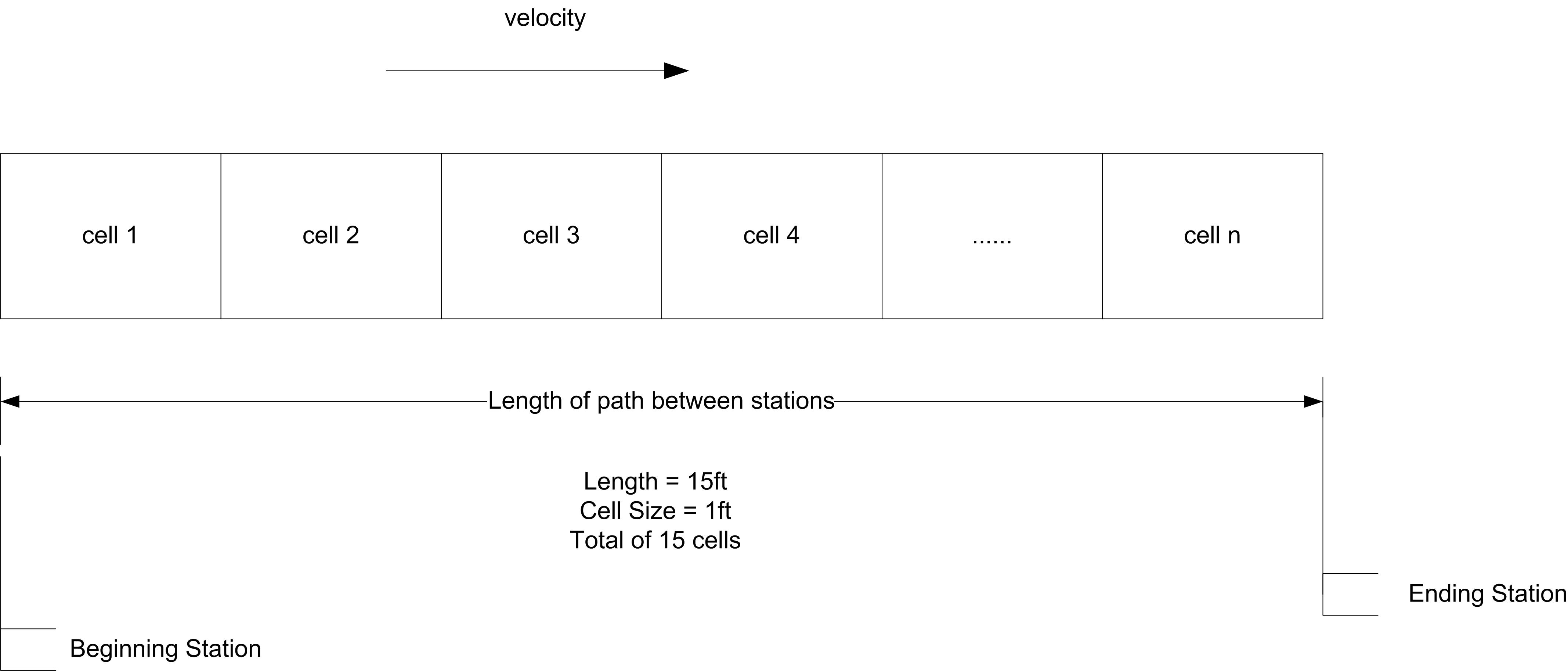
Figure 7.23: A conveyor conceptualized as a set of contiguous cells
In the figure, if each cell represents 1 foot and the total length of the conveyor is 15 feet, then there will be 15 cells. The cell size of the conveyor is the smallest portion of a conveyor that an entity can occupy. In modeling with conveyors, the size of the entity also matters. For example, think of people riding an escalator. Some people have a suitcase and take up two steps and others do not have a suitcase an only take up one step. An entity must acquire enough contiguous cells to hold their physical size in order to be conveyed.
The key modules for modeling the use of conveyors are:
- ACCESS
When an entity enters an ACCESS module, it will wait until the appropriate amount of contiguous cells are available at the access point. Once the entity has control of the cells, it can then be conveyed from its current station to a station associated with the conveyor. This is similar in concept to the ALLOCATE module for transporters.
- CONVEY
The CONVEY module causes the entity to move from its origin station to its next station. The time to move is based on the velocity of the conveyor and the distance between the stations. This similar in concept to the MOVE module for transporters.
- EXIT
The EXIT module causes the entity to release the cells that it holds on the conveyor. If another entity is waiting in queue for the conveyor at the same station where the cells are released, the waiting entity will then access the conveyor. This is like releasing a resource or freeing a transporter.
- START
The START module changes the status of the conveyor to active. Entities may reside on the conveyor while it is stopped. These entities will maintain their respective positions on the conveyor once it is started. The entity using the START module does not have to be on the conveyor.
- STOP
The STOP module changes the status of the conveyor to inactive. The conveyor will stop immediately, regardless of the number of entities on the conveyors. This is useful for modeling conveyor failures or blockages on the conveyor. The entity using the STOP module does not have to be on the conveyor.
- CONVEYOR
This data module defines whether or not the conveyor is an accumulating or non-accumulating conveyor, the cell size (in physical units e.g. feet), and the velocity. A conveyor consists of a sequence of segments as defined by the SEGMENT module. The sum of the distances among the stations on the conveyor (specified by SEGMENT module) must be divisible by the cell size. If not, an error will occur when the model is checked.
- SEGMENT
This data module defines the segment network that makes up a conveyor. Each segment is a directed link between two stations forming a network. The conveyor path is defined by a beginning station and a set of next station-distance pairs. The beginning station of the segment is the beginning station number or name, and the next station defines the next station name that is a length of distance units from the previously defined station. The length of the segment must be specified in integer distance units (feet, meters, etc.). No station should be repeated within the segment network unless the conveyor is a loop conveyor. In that case, the last ending station should be the same as the beginning station for the segment network.
As was the case for transporters, the ENTER and LEAVE modules of the advanced transfer template will also provide some conveyor functionality. LEAVE provides for ACCESS and CONVEY. ENTER provides for EXIT. The modules work slightly differently for accumulating and non-accumulating conveyors.
Non-accumulating conveyors travel in a single direction, and the spacing remains the same between the entities. When an entity is placed on the conveyor, the entire conveyor is actually disengaged or stopped until instructions are given to transfer the entity to its destination. When the entity reaches its destination, the entire conveyor is again disengaged until instructions are given to remove the entity from the conveyor, at which time it is engaged or started.
As previously mentioned, the conveyor is divided into a number of cells. To get on the conveyor and begin moving, the entity must have its required number of contiguous cells. For example, in Figure 7.24, the circle needed 1 cell to get on the conveyor. Suppose the hexagon was trying to get on the conveyor. As cell 2 became available, the hexagon would seize it. Then it would wait for the next cell (cell 1) to become available and seize it. After having both required cells, it is “on" the conveyor. But moving on a conveyor is a bit more continuous than this. Conceptually, you can think of the hexagon, starting to move on the conveyor when it gets cell 2. When one cell moves, all cells must move, in lock step. Since entities are mapped on to the cells by their size, when a cell moves the entity moves. Reversing this analogy becomes useful. Suppose the cells are fixed, but the entities can move. In order for an entity to”take a step" it needs the next cell. As it crosses over to the next cell it releases the previous cell that it occupied. It is as if the entity’s “step size” is 1 cell at a time.
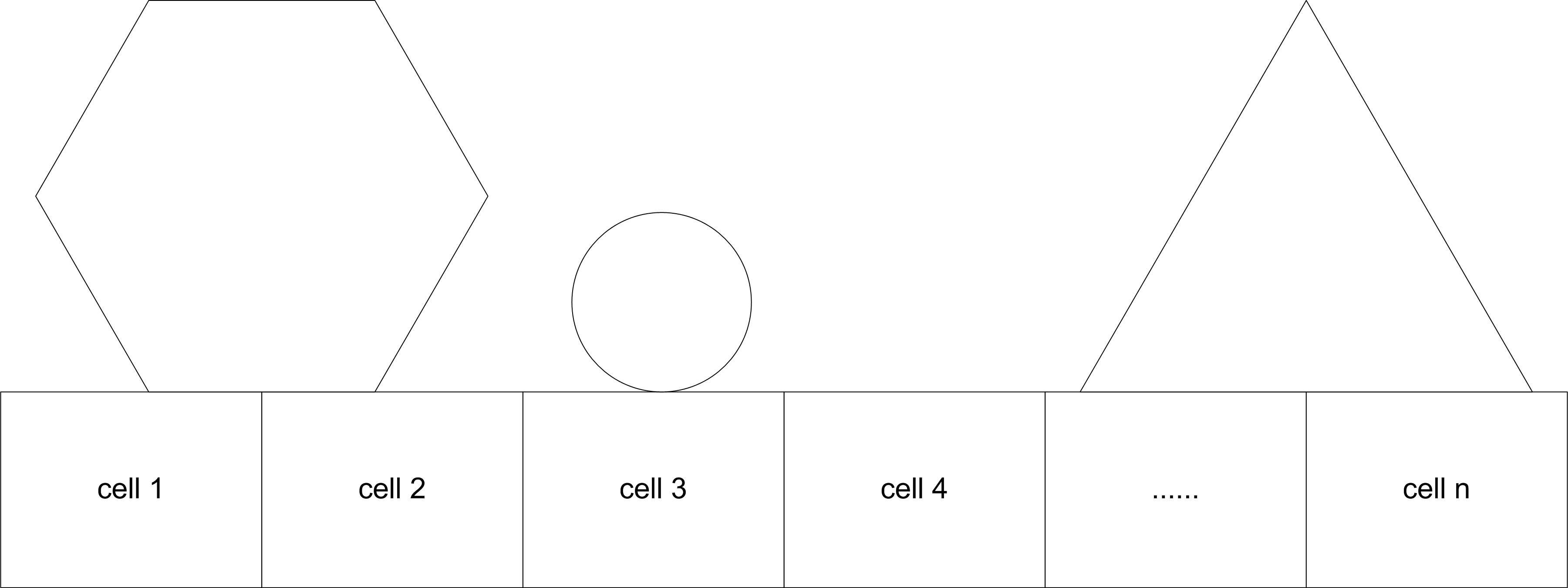
Figure 7.24: Different entity sizes on a conveyor
Figure 7.25 illustrates an approximate activity flow diagram for an entity using a non-accumulating conveyor. Suppose the entity size is 2 feet and each cell is 1 foot on the conveyor. There is a queue for the entities waiting to access the conveyor. The cells of the conveyor act as resources modeling the space on the conveyor. The movements of the entity through the space of each cell are activities. For the 2 foot entity, it first seizes the first cell and then moves through the distance of the cell. After the movement it seizes the next cell and moves through its length. Because it is 2 feet (cells) long it seizes the 3rd cell and then releases the first cell before delaying for the move time for the 3rd cell. As cells become released other entities can seize them and continue their movement. The repeated pattern of overlapping SEIZE and RELEASE modules that underlie conveyor modeling clearly depends upon the number of cells and the size of the entity. Thus, the activity diagram would actually vary by the size of the entity (number of cells required).
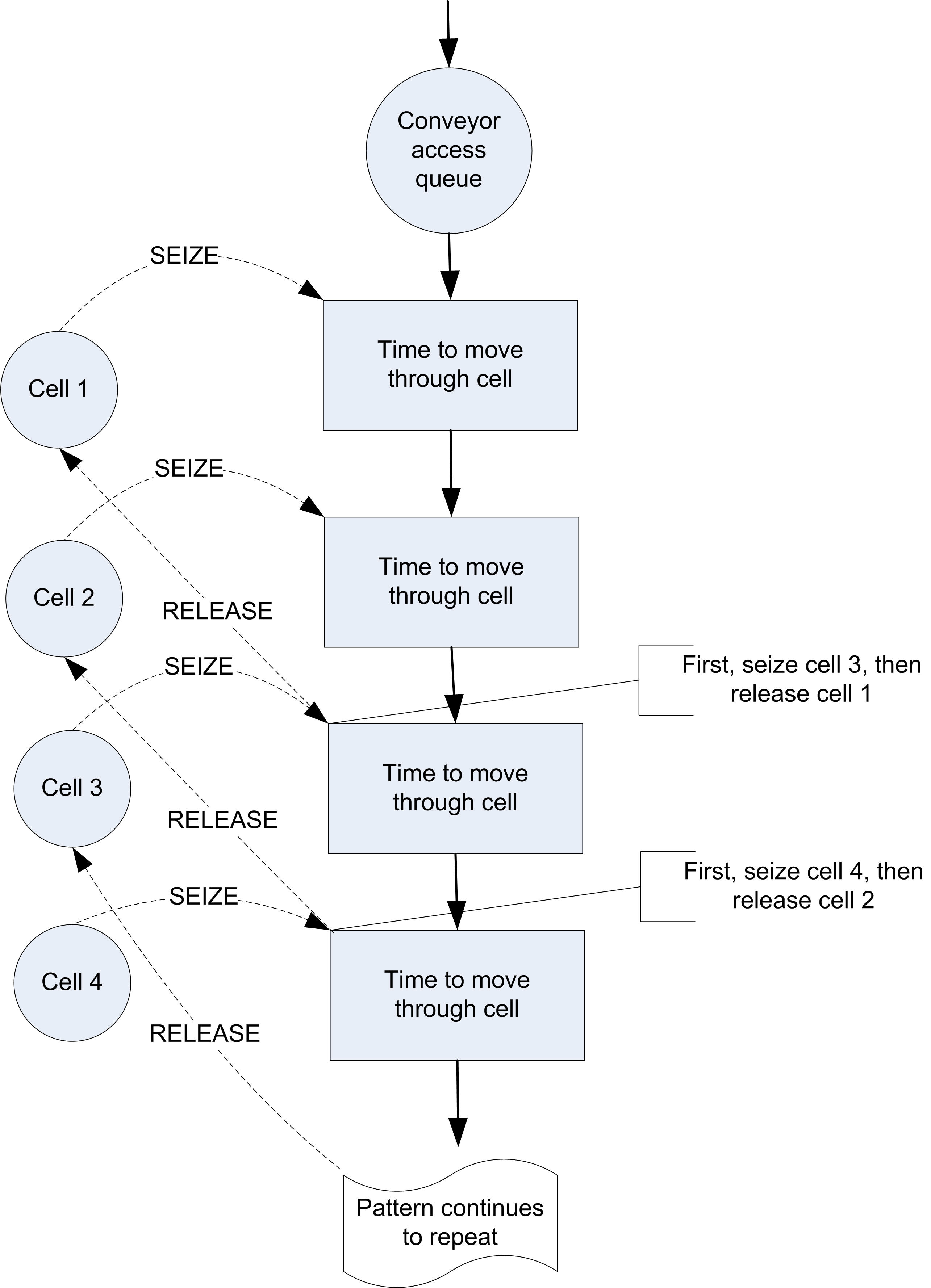
Figure 7.25: Activity diagram for non-accumulating conveyor
The larger the number of cells to model a segment of a conveyor the more slowly the model will execute; however, a larger number of cells allows for a more “continuous" representation of how entities actually exit and leave the conveyor. Larger cell sizes force entities to delay longer to move and thus waiting entities must delay for available space longer. A smaller mapping of cells to distance allows then entity to”creep" onto the conveyor in a more continuous fashion. For example, suppose the conveyor was 6 feet long and space was modeled in inches. That is, the length of the conveyor is 72 inches. Now suppose the entity required 1 foot of space while on the conveyor. If the conveyor is modeled with 72 cells, the entity starts to get on the conveyor after only 1 inch (cell) and requires 12 cells (inches) when riding on the conveyor. If the mapping of distance was 1 cell equals 1 foot, the entity would have to wait until it got a whole cell of 1 foot before it moved onto the conveyor.
Now you are ready to put these concepts into action.
7.3.1 Test and Repair Shop with Conveyors
For simplicity, the test and repair shop will be used for illustrating the use of conveyors. Figure 7.26 shows the test and repair shop with the conveyors and the distance between the stations. From the figure, the distances from each station going in clockwise order are as follows:
Diagnostic station to test station 1, 20 feet
Test station 1 to test station 2, 20 feet
Test station 2 to repair, 15 feet
Repair to test station 3, 45 feet
Test station 3 to diagnostics, 30 feet
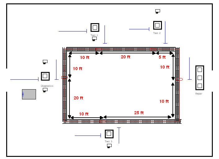
Figure 7.26: Test and repair shop with conveyors
Assume that the conveyor’s velocity is 10 feet per minute. These figures have been provided in this example; however, in modeling a real system, you will have to tabulate this information. To illustrate the use of entity sizes, assume the following concerning the parts following the four test plans:
Test plan 1 and 2 parts require 1 foot of space while riding on the conveyor
Test plan 3 and 4 parts require 2 feet of space while riding on the conveyor
The conveyor logic will first be implemented without animation. Then, the animation for the conveyors will be added. To convert the previous model so that it uses conveyors, the model, RepairShopWithTransportersNoAnimation.doe, should be changed as follows:
Delete the TRANSPORTER and DISTANCE modules defined for using the transporter
Delete the REQUEST and TRANSPORT modules for leaving the stations and replace them with LEAVE modules. The LEAVE modules will be filled out in a moment.
Add a variable array called
vSizes()of dimension 4 to hold the sizes of the parts following each of the test plans as shown in Figure 7.27.Save your file. The completed model can be found in the file RepairShopWithConveyorsWithNoAnimation.doe.
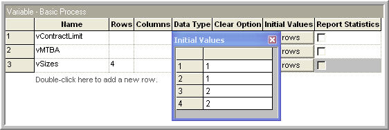
Figure 7.27: Array for part sizes
Now, you are ready to define the conveyor and its segments. You will first define the segments for the conveyor, then the conveyor itself. Figure 7.28 shows the segments to be used on the conveyor. First, give the segment a name and then specify the station that represents the beginning station. The beginning station is the station associated with the first segment of the conveyor. Since this is a loop conveyor, the beginning station is arbitrary. The diagnostic station is used here since this is where the parts enter the system.
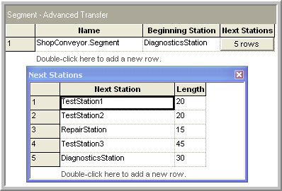
Figure 7.28: SEGMENT module for test and repair conveyor
Then, the next station and the distance to the next station are given for each part of the conveyor. Notice that the distances have been added as shown in Figure 7.26. The lengths specified in Figure 7.28 are in the actual physical distances (e.g. feet). The mapping to cells occurs in the CONVEYOR module.
Figure 7.29 shows the CONVEYOR module. To associated the conveyor with a segment use the Segment Name drop down box. The next decision is the type of conveyor. In this case, a non-accumulating conveyor should be used.
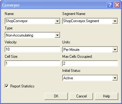
Figure 7.29: CONVEYOR module for test and repair example
The velocity of the conveyor is 10 feet per minute. Now, the cell size and the maximum cells occupied text-boxes must be completed. The cell size is the most important decision. Thinking back to Figure 7.25, it should be clear that space must be represented by discrete cells of a specified integral length. Thus, the total length of the conveyor must be integer valued and the cell size must result in an integer number of cells for each segment. The lengths of each distance specified in the SEGMENT module for the example are all divisible by 5. Thus, you could choose a cell size of 5. This would mean that each cell would be 5 feet in length. Since entities access the conveyor by grabbing cells, this hardly seems appropriate if the parts are 1 and 2 feet in length, respectively. In the case of a 5 foot cells size, the parts would have a lot of space between each other as they ride on the conveyor. Instead, the cell size will be specified as 1 foot. This will always work, since every number is divisible by 1. It also works well in this case, since the smallest part is 1 foot and the distances in the SEGMENT module are based on the units of feet. Now, the maximum number of cells text field is easy. This represents the size of the biggest entity in terms of cells. This should be 2 in this case since parts that follow test plans 3 and 4 are 2 feet in length.
With the CONVEYOR and SEGMENT modules defined, it is an easy matter to change the ENTER and LEAVE modules to use the conveyors. The first item to address is to make sure that each created part knows its size so that the size can be used in the LEAVE module. You can do this with the "Assign Test Plan" ASSIGN module as shown in Figure 7.30.
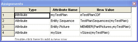
Figure 7.30: Assigning the size of the parts
The LEAVE modules must be updated to use the conveyor to transfer out
and to indicate the number of cells required by the entity. This is done
in Figure 7.31 using the entity’s mySize attribute.
Each of the other LEAVE modules for the other stations should be updated
in a similar fashion. Now, you must update the ENTER module so that the
entity can exit the conveyor after arriving to the desired station.
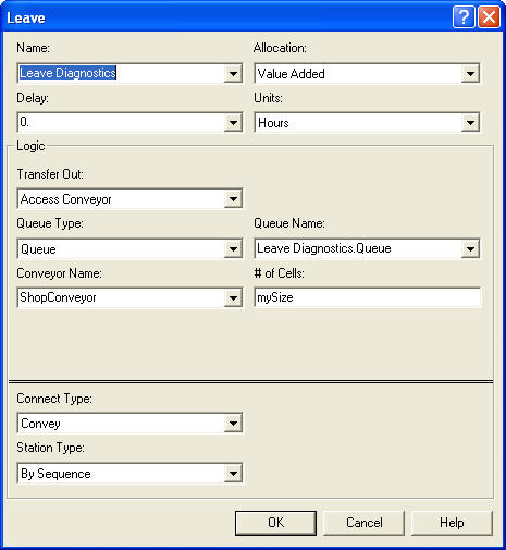
Figure 7.31: LEAVE module for test and repair example
In Figure 7.32, the Exit Conveyor option is used when transferring into the Test 1 Station. In both of the ENTER and LEAVE modules, the option of delaying the entity is available. This can be used to represent a loading or an unloading time for the conveyor.
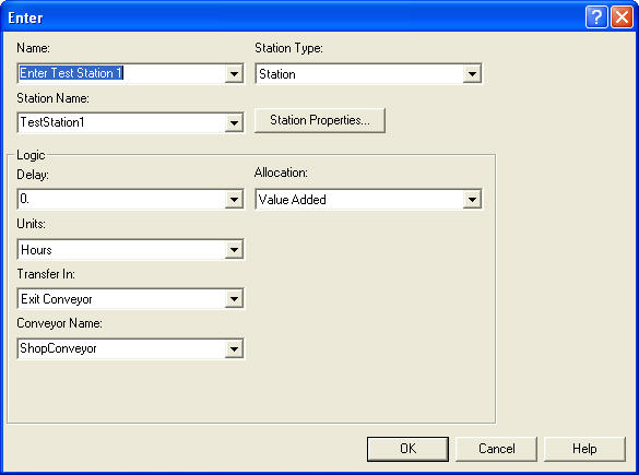
Figure 7.32: ENTER module for test station 1
With the conveyor statistics check-box clicked, the conveyor statistics will appear on the summary reports. See Figure 7.33. The utilization is calculated for the conveyor, regardless of conveyor type. This utilization represents the length of entities on the conveyor in comparison to the length of the entire conveyor over the simulation run. Thus, conveyor utilization is in terms of the space utilized. In addition, there is very little queuing for getting on the conveyor. The statistics for the conveyor in this problem indicate that the conveyor is not highly utilized; however, the chance of meeting the contract limit is up to 80%. The volumes in this example may make it difficult to justify the use of conveyors for the test and repair shop. Ultimately, the decision would come down to a cost/benefit analysis.
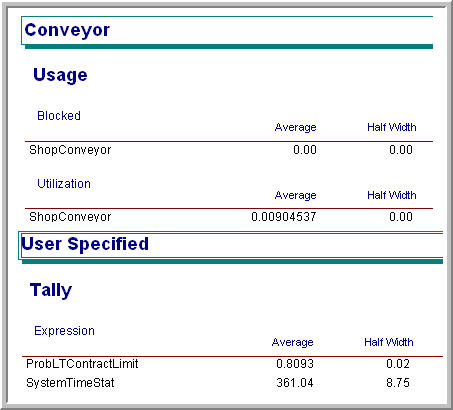
Figure 7.33: Statistics for test and repair shop with conveyors
7.3.2 Animating Conveyors
To augment the model with animation, the Animate Transfer toolbar can be used. To visibly discern the plan that an entity is following within the animation, you can define a picture set, with appropriately drawn pictures for each type of plan. This is illustrated in Figure 7.34 and Figure 7.35. The assignment to the Entity.Picture attribute is shown in Figure 7.39.
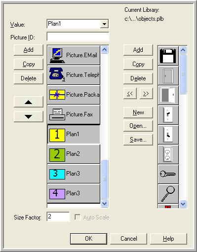
Figure 7.34: Enity pictures for test plans
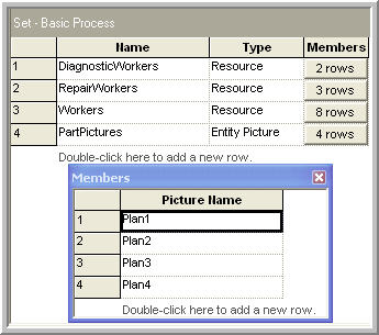
Figure 7.35: Picture set for test plans
To update the previous transporter animation, perform the following steps.
Copy and paste the animation elements from the file, RepairShopWithTransportersWithAnimation.doe to your own model file. The completed model is called, RepairShopWithConveyorsWithAnimation.doe.
Delete the transporter picture, station markers, and distance connectors.
Using the Animate Transfer toolbar’s Segment button make station markers and segment connectors to represent the conveyors as shown in Figure 7.26. The segment animation dialog is shown in Figure 7.36. It works very much like the route and distance animation dialog.
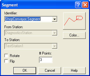
Figure 7.36: Segment animation dialog
After the segments have been laid down, you might want to place some lines to represent the conveyors. This was done in Figure 7.36 where the roller pattern from the line patterns button on the drawing toolbar was also used. That’s it! Animating conveyors is very easy. If you run the model with the animation on you will see that the entities move along the conveyor segments, getting on and off at the appropriate stations. You will also clearly see that for the majority of time the conveyor does not have very many parts. This section concentrated on non-accumulating conveyors. The next section describes how accumulating conveyors operate and discusses a number of other conveyor modeling issues.
7.3.3 Miscellaneous Issues in Conveyor Modeling
This section discusses accumulating conveyors, how to model merging conveyors, diverging conveyors, how to allow processing to occur on the entity while it is still on the conveyor, and re-circulation conveyors.
7.3.3.1 Accumulating Conveyors
An accumulating conveyor can be thought of as always running. When an entity stops moving on the conveyor (e.g. to unload), other entities are still allowed on the conveyor since the conveyor continues moving. When entities on the conveyor meet up with the stopped entity, they stop, and a queue accumulates behind the stopped entity until the original stopped entity is removed or transferred to its destination.
As an analogy, imagine wearing a pair of roller blades and being on a people mover in an airport. Don’t ask how you got your roller blades through security! While on the people mover you aren’t skating (you are standing still, resting, but still moving with the people mover). Up ahead of you, some seriously deranged simulation book author places a bar across the people mover. When you reach the bar, you grab on. Since you are on roller blades, you remain stationary at the bar, while your roller blades are going like mad underneath you.
Now imagine all the people on the mover having roller blades. The people following you will continue approaching the bar until they bump into you. Everyone will pile up behind the bar until the bar is removed. You are on an accumulating conveyor! Notice that while you were on the conveyor and there was no blockage, the spacing between the people remained the same, but that when the blockage occurred the spacing between the entities decreased until they bump up against each other. To summarize:
Accumulating conveyors are always moving.
If an entity stops to exit or receives processing on the conveyor, other entities behind it are blocked and begin to queue up on the conveyor.
Entities in front of the blockage continue moving.
When a blockage ends, blocked entities, may continue, but must first wait for the entities immediately in front of them to move forward.
In modeling accumulating conveyors, the main differences occur in the actions of the ACCESS and CONVEY modules. Instead of disengaging the conveyor as with non-accumulating conveyors the conveyor continues to run. ACCESS allocates the required number of cells to any waiting entities as space becomes available. Any entities that are being conveyed continue until they reach a blockage. If the blocking entity is removed or conveyed, the accumulated entities only start to move when the required number of cells becomes available.
In the ACCESS module the number of cells still refers to the number of cells required by the entity while moving on the conveyor; however, you must indicate what the space requirements will be when the entities experience a blockage. In the CONVEYOR module, if the accumulating conveyor option is selected, the user must decide on how to fill in the Accumulation Length text field. The accumulation length specifies the amount of space required by the entities when accumulating. It does not need to be the same as the amount of space implied by the number of cells required when the entity is being conveyed. Also, it doesn’t have to be divisible into an even number of cells. In addition, as can be seen in Figure 7.37, the accumulation length can also be an entity (user defined) attribute. Thus, the accumulation size can vary by entity. Typically, the space implied by the number of cells required while moving will be larger than that required when accumulating. This will allow spacing between the entities when moving and allow them to get closer to each other when accumulating.
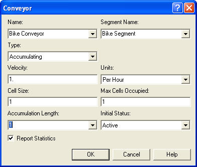
Figure 7.37: Accumulating conveyor dialog
The test and repair example barely required non-accumulating conveyors. Thus, to illustrate accumulating conveyors, a SMART file, (Smarts101.doe), will be used. See Figure 7.38. The SMART files can be found within the folder within your Arena installation.
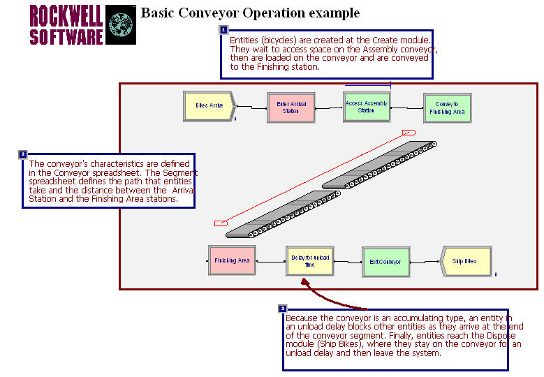
Figure 7.38: Arena Smarts101.doe model for accumulating conveyors
In this example, there is 1 segment for the conveyor of length 10, which (while not specified in the model) can be assumed to be in meters. The velocity is only 1 meter per hour, the conveyor cell size is 1, and the maximum size of an entity is 1. The entities, which are bicycles, enter at the arrival station and access the conveyor, where they are conveyed to the finishing area. You can think of the bicycles as being assembled as they move along the conveyor. This type of system often occurs in assembly lines. Once the bicycles reach the finishing area, they experience an unload delay prior to exiting the conveyor. Because the unload delay occurs prior to exiting the conveyor, the entity’s movement is blocked and an accumulation queue will occur behind the entity on the conveyor. You should run the model and convince yourself that the bicycles are accumulating.
When modeling with accumulating conveyors, additional statistics are collected on the average number of accumulating entities if the conveyors check-box is checked on the Project Parameters tab of the Run Setup dialog box. You can check out the help system to see all the statistics.
7.3.3.2 Merging and Diverging Conveyors
In conveyor modeling a common situation involves one or more conveyors feeding another conveyor. For example in a distribution center, there may be conveyors associated with each unloading dock, which are then attached to a main conveyor that takes the products to a storage area. To model this situation within , the feeding conveyors and the main conveyor can be modeled with different CONVEYOR modules and separate SEGMENT definitions. In this distribution center example, an item accesses the unloading dock’s conveyor rides the length of the conveyor and then attempts to get on the main conveyor. After it has accessed the main conveyor, the entity exits its current unloading dock conveyor.
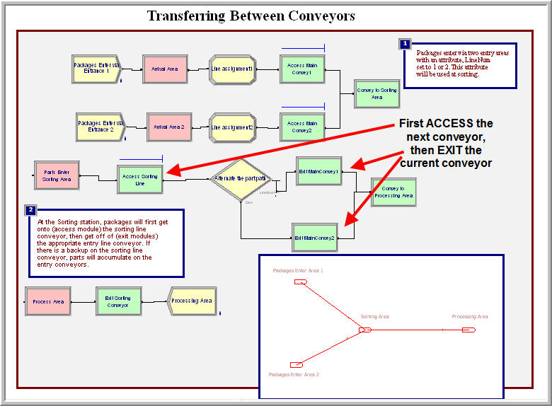
Figure 7.39: Transferring between conveyors
Arena has two SMART files that illustrate these concepts. Let’s first take a
look at Smarts107.doe. Figure 7.39 illustrates the overall model.
There are two conveyor lines for area 1 and area 2, respectively. When
the entities arrive to their area, an attribute called LineNum is
assigned to indicate where it came from. The entities access the
appropriate conveyor and then are conveyed to the sorting area. The
sorting area in this example is the station where the main conveyor
begins. Once the parts arrive at the sorting station, they first access
the conveyor to the processing area. Then, the entity exits its current
conveyor. The DECIDE module is used to select the correct conveyor to
exit based on the LineNum attribute. By first accessing the next
conveyor, the entity may have to wait on its current conveyor. Because
of this, it is very natural to model this situation with accumulating
conveyors. The feeder conveyors will back up as entities try to get on
the main conveyor.
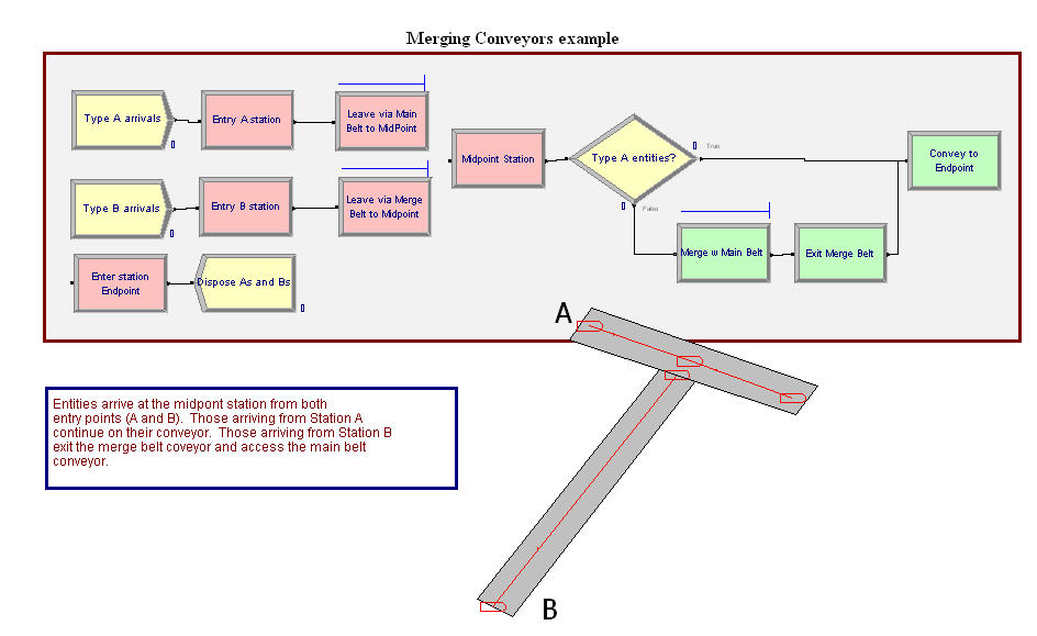
Figure 7.40: One conveyor merging into another
A similar example, Figure 7.40, involves the merging of one conveyor onto anther conveyor as in SMART file, Smarts110.doe. In this example, there are two conveyors. The main conveyor has two segment lengths associated with it. For example, the main conveyor goes from Entry A Station to the Midpoint Station to the EndPoint station, with lengths 5 feet respectively. The second conveyor is a single conveyor from the Entry B station to the MidPoint Station with a length of 10 feet. Notice that the MidPoint station is associated with segments related to the two conveyors. In other words, they share a common station. The entities arrive at both the Entry A and Entry B stations. Entities that arrive at the Entry A station first convey to the MidPoint station and then immediately convey to the EndPoint station. They do not exit the conveyor at the MidPoint station. Entities from the Entry B station are conveyed to the MidPoint station. Once at the MidPoint station they first ACCESS the main conveyor and then EXIT their conveyor. This causes entities coming from Entry B to potentially wait for space on the main conveyor. This basic idea can be expanded to any number of feeder conveyors along a longer main conveyor.
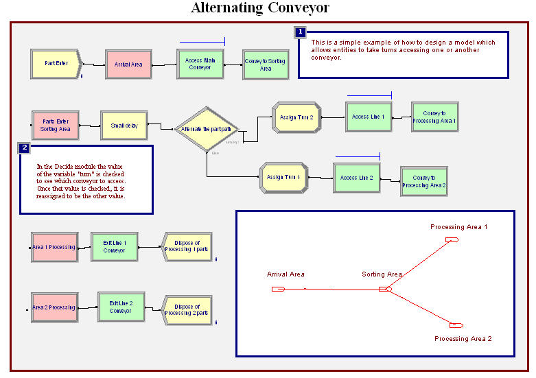
Figure 7.41: Simple alternating conveyor
Diverging conveyors are often used in system that sort items. The items come in on one main conveyor and are transferred to any number of other conveyors based on their attributes (e.g. destination). Arena’s Smarts108.doe file illustrates the basic concepts behind diverging conveyors. In this example, as shown in Figure 7.41, the parts arrive to the arrival area and access a conveyor to the sorting area. Once an entity reaches the sorting station, the entity first exits the incoming conveyor and then there is a small delay for the sorting. The module labeled “Parts Enter Sorting Area” is an ENTER module with the transfer in option used to exit the conveyor. Then the entity is shunted down one of the lines based on a DECIDE module. In this model, a variable is used to keep track of the last line that an entity was sent to so that the other line will be used in the DECIDE for the next entity. This implements a simple alternating logic. After being shunted down one of the conveyors, the entity uses the standard ACCESS, CONVEY, STATION, EXIT logic before being disposed.
With a little imagination a more sophisticated sorting station can be implemented. For example, number of conveyors that handle the parts by destination might be used in the system. When the parts are created they are given an attribute indicating their destination station. When they get to the sorting station, a DECIDE module can be used to pick the correct conveyor handling their destination.
7.3.3.3 Processing while on the Conveyor
In the bicycle example from Smarts101.doe, the workers can be conceptualized as moving along with the conveyor as they assemble the bicycles. In many systems it is common for a machine to be positioned to use the surface of the conveyor as its work area. For example, in circuit board manufacturing, the circuit boards ride on a conveyor through chip placement machines. While in the machine, the conveyor stops to do the insertion. These types of situations can be easily modeled in by not exiting the conveyor while undergoing a PROCESS module.
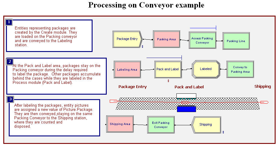
Figure 7.42: Processing while on a conveyor
Arena’s SMART file, Smarts103.doe, contains an example of this type of modeling. In this example, as shown in Figure 7.42, packages are created for the packing area, where they access and convey on a conveyor to the pack and label station. The conveyor consists of two segments attached at the pack and label station. Once at the Labeling Area station the entity enters a PROCESS module, which requires a delay and the labeling machine. Notice that the entity did not exit the conveyor. The "Loading Area" module is a simple STATION module. After completing the processing, the entity proceeds to be conveyed to the shipping area, where it exits the conveyor. In this example, the conveyor is a non-accumulating conveyor. If you run the model, you will see that the whole conveyor stops when the entity is being processed. If an accumulating conveyor is used, the packages would queue up behind the labeling machine.
7.3.3.4 Recirculating Conveyors
A recirculating conveyor is a loop conveyor in which the entities may ride on the conveyor until there is adequate space at their desired location. In essence the conveyor is used as space to hold the entities that cannot get off due to inadequate space at the necessary station. For example, suppose that in the test and repair shop there was only space for one waiting part at test station two. Thus, the size of test station two’s queue can be at most 1.
The previous model can be easily modified to handle this situation by not using an ENTER module at test station 2. Figure 7.43 shows the changes to the logic for test station 2 to handle this situation. As can be seen in the figure, the ENTER module has been replaced with a combination of STATION, DECIDE, EXIT, and CONVEY. The DECIDE module checks the queue at the Testing Process 2 module. If a part is not in the queue, then the arriving part can exit the station and try to seize the testing resources. If there is a part waiting, then the arriving part is sent to the CONVEY module to be conveyed back around to test station 2. As long as there is a path back to the station, this is perfectly fine (as in this case). The modified model is available with the files for this chapter in the file called RepairShopWithRecirculatingConveyorsWithAnimation.doe. If you run the model and watch the animation, you will see much more parts on the conveyor because of the re-circulation.
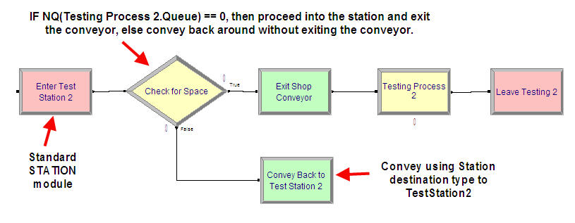
Figure 7.43: Test and repair shop with recirculating conveyor
There are still a number of issues related to conveyor modeling that have not discussed, especially the use of the specialized variables defined for conveyors. You should refer to the Arena’s Variables Guide or to Arena’s help system under conveyor variables for more information on this topic. also has a number of other SMART files that illustrate the use of conveyors. For example, you might want to explore SMART file, Smarts105.doe, to better understand entity size and how it relates to cells on the conveyor. Conveyors allow the modeling of space through the used of cells. The next section examines how Arena models space when it is relevant for transporter modeling.