7.1 Resource Constrained Transfer
When an entity requires the use something to complete the movement between stations, Arena’s RESOURCE module can be used to model the situation. In this situation, the physical (e.g. distance) aspects of the movement are not of interest, only the time that may be constrained by the availability of the transport mechanism. To illustrate this modeling, let’s revisit the test and repair shop from Chapter 4.
Recall that in the test and repair shop, parts follow 1 of 4 different test plans through the shop. Each part first goes to the diagnostic station where it determines the sequence of stations that it will visit via an assignment of a test plan. After being diagnosed, it then proceeds to the first station in its test plan. In the example of Chapter 4, it was assumed that a worker (from somewhere) was always available to move the entity to the next station and that the transfer time took between 2-4 minutes uniformly distributed. The diagnostic station had two diagnostic machines and each test station had 1 testing machine. Finally, the repair station had 3 workers that performed the necessary repairs on the parts after testing. An implicit assumption in the model was that there was a worker staffing each of the two diagnostic machines (1 worker for each machine) and that there was a worker assigned to each test station. The modeling of the workers was not a key component of the modeling so that such an implicit assumption was fine.
In this section, the use of the workers to move the entities and to staff the stations will be explicitly modeled. Assume that there are 2 workers at the diagnostic station, 1 worker per testing station, and 3 workers at the repair station. Thus, there are a total of 8 workers in the system. For simplicity, assume that any of these 8 workers are capable of moving parts between the stations. For example, when a part completes its operation at the diagnostic station, any worker in the system can carry the part to the next station. In reality, it may be useful to assign certain workers to certain transfers (e.g. diagnostic workers move parts to the part’s first station); however, for simplicity these issues will be ignored and any worker will be allowed to do any transport in this example. This also requires that any worker is capable of noticing that a part needs movement. For example, perhaps the part is put in a basket and a light goes on indicating that the part needs movement. When a part requires movement, it will wait for the next available idle worker to complete the movement. In this situation, a worker may be busy tending to a part in process at a station or the worker may be busy moving a part between stations. Figure 7.1 illustrates the new situation for the test and repair shop involving the use of workers.
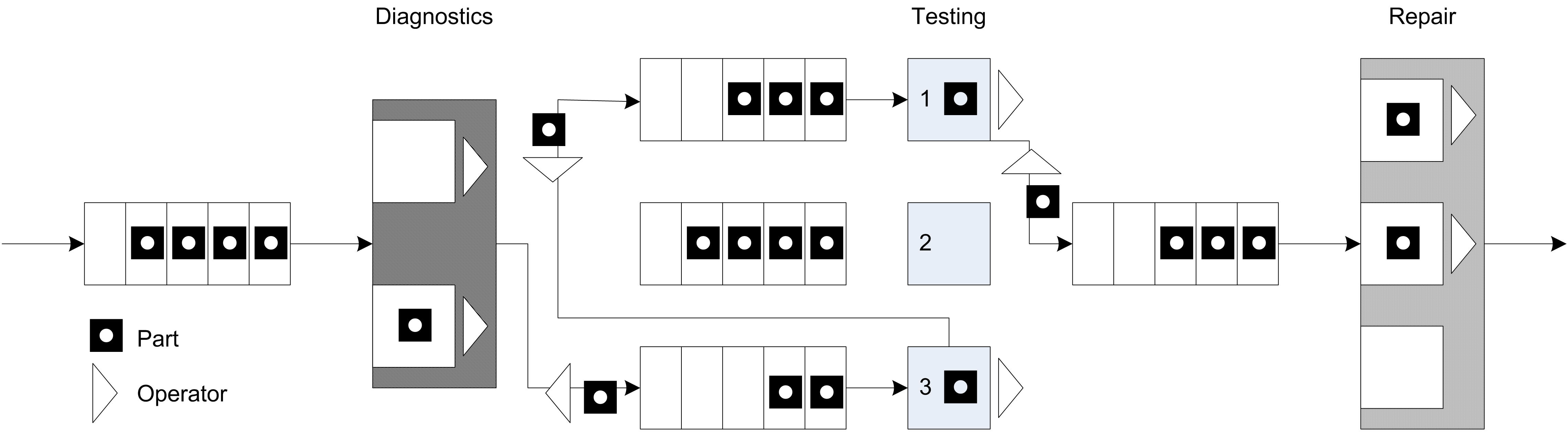
Figure 7.1: Test and repair shop with workers providing the movement
Since workers are required for the processing of parts at the stations and they might have to perform the movement of parts between stations, the workers must be shared between two activities. Thus, when a worker completes one activity a mechanism is needed to indicate which activity should proceed next. A simple mechanism is to assign a priority to one of the tasks. Thus, it seems reasonable to assume that parts waiting for processing at a station are given priority over parts that require movement between stations.
Figure 7.2 illustrates an activity diagram for the situation where the workers are called for the transport. In the figure, each worker is indicated individually. For example, DW1 refers to worker 1 at the diagnostic station. In the figure, the visitation of each part to a different test station is illustrated with a loop back to the transfer time after the testing delay. Thus, the figure represents all three test stations with the test station queue, testing delay, and test machine combination. Unfortunately, this does not explicitly indicate that a test worker is assigned to each test station individually. In particular, the other resources marked TW2 and TW3 should technically have seize and release arrows associated with them for the testing activity at a particular station.
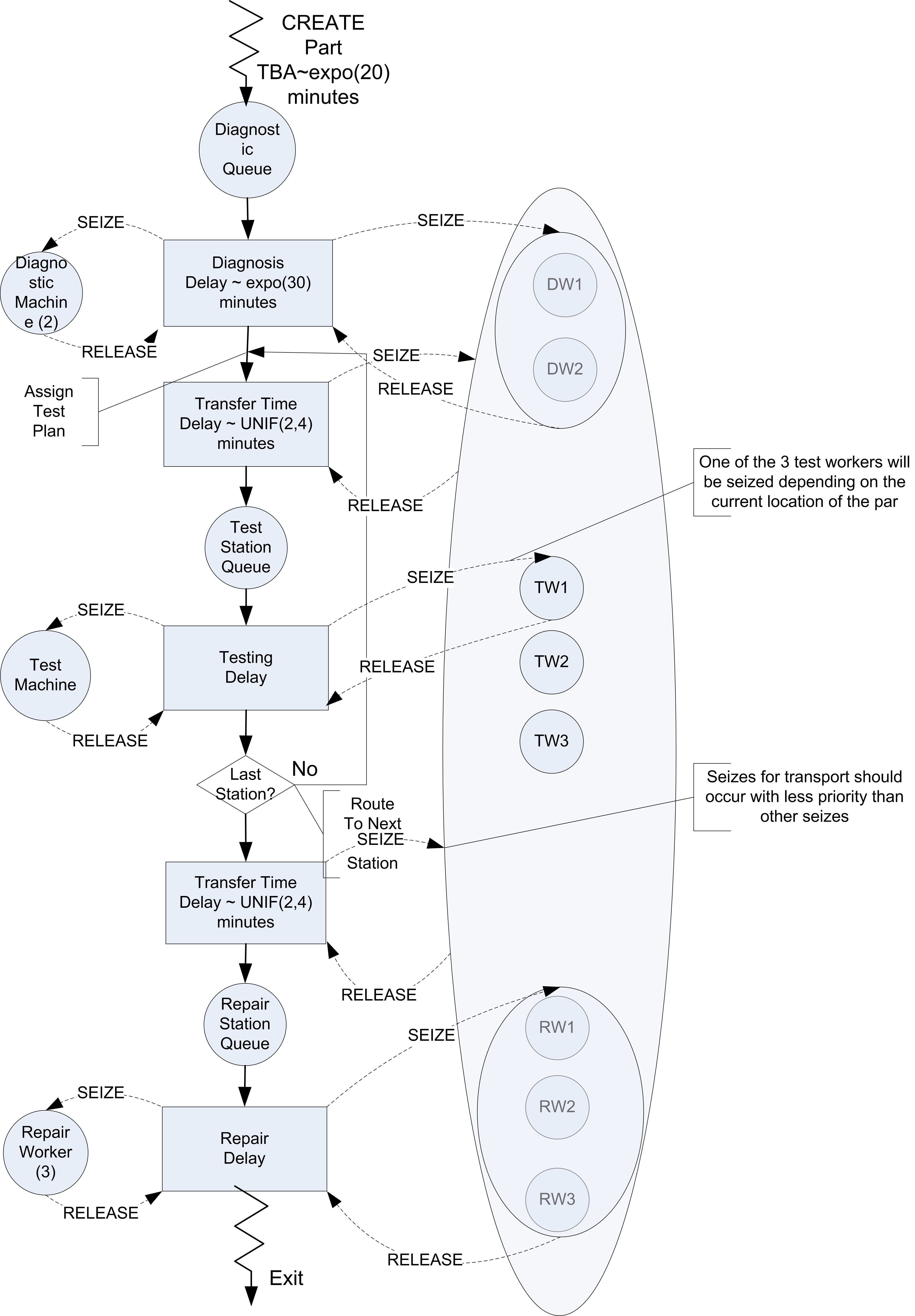
Figure 7.2: Activity diagram for revised test and repair situation
It should be clear from the figure that three sets of resources will be required in this model. A resource set should be defined for the diagnostic workers with two members. A resource set should be defined for the three repair workers. Finally, a resource set should be defined to hold each of the workers DW1, DW2, TW1, TW2, TW3, RW1, RW2, RW3 that are available for transporting parts. When a part requires diagnostics, it will seize one of the workers in the diagnostic workers set. When a part requires testing, it will seize the appropriate test worker for its current station. Finally, at the repair station, the part will seize one of the repair workers. In order to receive transport, the part will seize from the entire worker set.
7.1.1 Implementing Resource Constrained Transfer
Based on Figure 7.2, the basic pseudo-code for resource constrained transfer should be something like that shown in the following pseudo-code.
CREATE part
SEIZE 1 diagnostic machine
SEIZE 1 diagnostic worker from diagnostic worker set
DELAY for diagnostic time
RELEASE diagnostic machine
RELEASE diagnostic worker
ASSIGN test plan sequence
SEIZE 1 worker from worker set
ROUTE for transfer time by sequence to STATION Test

STATION Test
RELEASE worker
SEIZE appropriate test machine
SEIZE appropriate test worker
DELAY for testing time
RELEASE test machine
RELEASE test worker
SEIZE 1 worker from worker set
DECIDE
    IF not at last station
        ROUTE for transfer time by sequence to STATION Test
    ELSE
        ROUTE for transfer time by sequence to STATION Repair
    ENDIF
END DECIDE

STATION Repair
RELEASE worker
SEIZE repair worker from repair worker set
DELAY for repair time
RELEASE repair worker
RECORD statistics
DISPOSE
This logic assumes that each worker has been placed in the appropriate sets. At the diagnostic station both the machine and a diagnostic worker are required. When the part completes the processing at the diagnostic station, the part seizes a worker from the overall set of workers and routes with a transfer delay to the appropriate testing station.
After arriving at the test station, the part releases the worker that performed the transport and proceeds with the seizing of the test machine and worker. Again, prior to the routing to the next station, a worker from the overall set of workers is seized. Notice also that the worker is released after the part is transferred to the repair station.
The combination of logic (SEIZE, ROUTE, STATION, RELEASE) is very common in entity transfer modeling. While this logic can be directly implemented with the corresponding modules, has provided two additional modules that enable a wide range of transfer modeling options through dialog box entries. These modules are the ENTER and LEAVE modules of the Advanced Transfer panel. The ENTER module represents a number of different modules based on how its dialog box entries are completed. Essentially, an ENTER module represents the concepts of a STATION, a delay for unloading, and the releasing of the transfer method. Within the LEAVE module, the user can specify a delay for loading, how the entity will be transferred out (e.g. resource, conveyor, transporter), and the routing of the entity. Now let’s take a look at how to modify the test and repair model from Chapter 4 to use these new constructs.
Starting with a copy of the RepairShop.doe file from Chapter 4, the first step is to define 8 individual resources for the diagnostic workers (2), the test workers (1 for each station), and the repair workers (3). This is illustrated in Figure 7.3, where the workers have been added to the RESOURCE module. Notice that the repair workers have been changed from having a single resource with capacity 3 to three resources each with capacity 1. This will enable all eight workers represented as resources to be placed in an overall worker(resource)set.
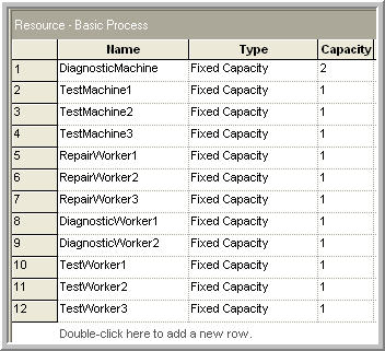
Figure 7.3: Resources for test and repair shop
Use the SET module on the Basic Process panel to define each of the three sets required for this problem. Figure 7.4 illustrates the Workers set within the SET module. The DiagnosticWorkers and RepairWorkers sets are defined in a similar manner using the appropriate resources. Since there was no preference given in the use of the resources within the sets just listed them as shown. Recall that for the preferred resource selection rule, the order of the resources matters. The cyclical rule is used in this model.
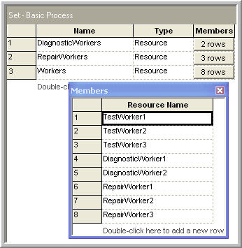
Figure 7.4: Resource sets for test and repair shop
Now that the new resources and their sets have been defined, you need to update each of the PROCESS modules in order to ensure that the appropriate resources are seized and released. This is illustrated in Figure 7.5. In the Diagnostic Process dialog, the SEIZE-DELAY-RELEASE option has been used with the list of resources required. In this case, the part needs both 1 unit of the diagnostic machine and 1 unit of from the DiagnosticWorkers set. Each of the testing stations is done in a similar manner by first seizing the test machine and then seizing the test worker. The repair station is done in a similar fashion, except there is only the seizing of 1 unit from the RepairWorkers set. In all cases, the cyclical rule is used with the level of medium for the seize priority. If you are following along with the model building process, you should update each of the PROCESS modules as described. The completed model is found in the file RepairShopResourceConstrained.doe that accompanies this chapter.
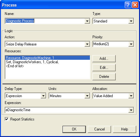
Figure 7.5: Seizing with the diagnostic process
Now the ENTER and LEAVE modules can be specified. The STATION modules associated with the 3 testing stations and the repair station will be replaced with appropriately configured ENTER modules. In addition, the ROUTE modules will be replaced with LEAVE modules for routing to the testing stations, between the testing stations, and to the repair station. Let’s start with specifying how to leave the diagnostic station. Delete the ROUTE module associated with the diagnostic station and drag a LEAVE module into its place. Then fill out the LEAVE module as shown in Figure 7.6.
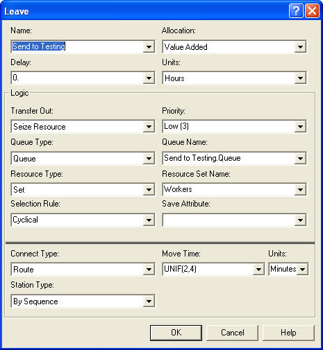
Figure 7.6: LEAVE module for test and repair shop
When you first open the LEAVE module, it will not look as shown in the figure. As can be seen in the figure, it is divided into three components: Delay, Logic (Transfer Out), and Connect Type. The Delay text field allows a time delay to be specified after getting the transfer out option. This can be used to represent a loading time. In this case, the loading time will be ignored (it takes negligible time for the worker to pick up the part). The transfer out logic allows the specification of the use of a transporter, a conveyor, a resource, or no constrained transfer (none). In this case, the seize resource option is required.
After selecting one of the resource constrained transfer options, additional options will become available. Because the transfer is constrained, the entity must have a place to wait for the transfer if the resource is not immediately available. Thus, there is the option to specify a queue for the entity. You can think of this queue as the output bin for the station. Just like in the PROCESS module, you can directly seize a resource or seize a resource from a resource set. In this case, one worker will be seized from the Workers set. Notice that a low seize priority has been specified. Since this priority is lower than that used by the parts when seizing with the PROCESS modules, the PROCESS modules will have higher priority when parts are waiting for processing over those waiting for transfer.
Finally, the Connect Type option within the LEAVE module is just like the corresponding options in the ROUTE module. In this case, the entity can be routed by sequence with a routing delay of UNIF(2,4) minutes. Each of the other ROUTE modules in the previous model should be replaced with LEAVE modules like that shown in Figure 7.6. To do this replacement quicker, you can simply delete the ROUTE modules and copy/paste LEAVE modules as per Figure 7.6. You should make sure to change the name of the modules after the cut/paste operation, since no two modules can have the same name.
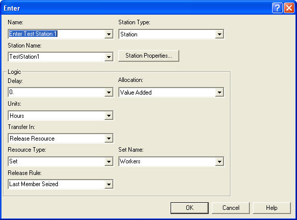
Figure 7.7: ENTER module for test and repair shop
Now, the ENTER module can be specified. The ENTER module for test station 1 is given in Figure 7.7. Again, the ENTER module allows a composition of a number of other modules by having a Station Name and Logic options. Within the Logic options, you can specify a delay and the transfer in options. The Delay option represents a delay that occurs prior to the transfer in option. This is commonly used to represent a delay for unloading the transferring device. In this model, the time to unload (put down the part) is assumed to be negligible for the worker.
The transfer in option indicates how the entity should react with respect to the transfer mechanism. There are four options (Free Transporter, Exit Conveyor, Release Resource, and None). A simple unconstrained transfer uses the None option. In this model, the release resource option should be used. Since the worker that was seized for the transfer was part of a set, you can select the set option for the resource type. The release rule specifies how the resource will be released. In this case, the last member seized option should be used. This means that the most recent member of the Workers set that the part seized will be released.
Similar to what was done in Chapter 4, the model was run for 10 replications of 4160 hours to examine the effect on the performance measures. As can be seen in Figure 7.8, the probability of meeting the contract specification has been reduced by about 10% (from 82.51% in Chapter 4 to 72.04% in this example). This is due to the increase in the average system time.
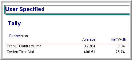
Figure 7.8: Probability of meeting the contract requirements
As can be seen in Figure 7.9, the time spent waiting in the station’s output buffer for pick up ranges from 13-15 minutes. Since there are 4 queues, this time has added significantly to the system time of the parts. In Figure 7.10, the utilization of the resources is relatively high (near 90% in most cases).
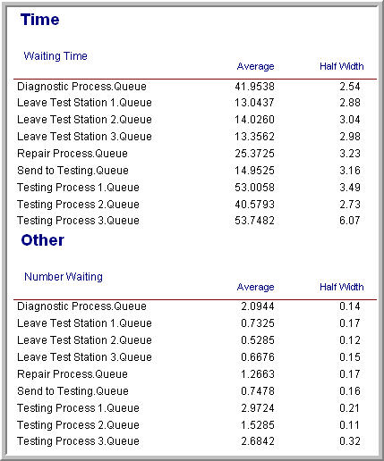
Figure 7.9: Queue statistics for test and repair shop with resource constrained transfer
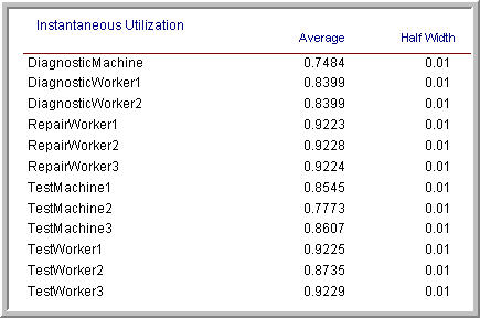
Figure 7.10: Utilization statistics for test and repair shop with resource constrained transfer
Because of the increased risk of not meeting the contract specifications for the system modeled with the more realistic use of workers to transfer parts, it might be useful to consider alternative ways to transfer the parts between stations. The next section examines the use of dedicated workers modeled as transporters to perform this work. Before proceeding with that modeling, the animation needs to be enhanced.
7.1.2 Animating Resource Constrained Transfer
If you ran the model of the previous section with the animation turned on you would notice the queues for the PROCESS modules and for the ROUTE modules. Unfortunately, you cannot see the entities during the transfer between stations. In this section, you will augment the basic flow chart animation with route animation, so that the flow of the entities between the stations will be visible. The animation of the stations will also be updated. Unfortunately, to really represent the use of the resources well within the animation, more effort would need to be expended on the animation than is useful at this time. For example, workers can be busy tending a process or walking. To properly represent this, the definition of additional resource states and their animation would need to be discussed. As will be covered in the next section, the use of transporters will greatly assist in that regard. Thus, for simplicity, the movement of the entities between the stations and will have a rather crude representation of the resource usage.
Figure 7.11 shows the final animation for the model. The completed model is available in the file, RepairShopResourceConstrainedTransferWithAnimation.doe. The key new animation concept that needs to be introduced is the Animate Transfer toolbar. Notice that in the figure, the toolbar has been detached. The two key buttons that will be used are the Station Marker button and the Route connector button.
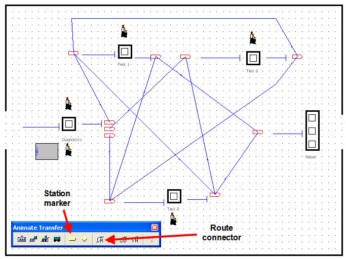
Figure 7.11: Final animation for resource constrained transfer
An overview of how to create this animation starting from the file RepairShopResourceConstrainedTransfer.doe is as follows:
Use Arena’s drawing toolbar to place the dark lines for the outline of the repair shop and for the dark rectangles to represent the stations. Use the text label button to label each of the station areas.
Use the Resource button on the Basic Animate toolbar to place each of the resources (Diagnostic machines, test machines, repair workers, diagnostic workers, and test workers). In the figure, the standard animation for resources was used to represent the diagnostic machines, the test machines, and the repair workers. The picture library (as described in Chapter 2) was used to assign a seated worker to the idle picture and a worker that looks to be walking to the busy state of the diagnostic and test workers.
Delete the queues from the flow chart area and re-add them using the Queue button of the Basic Animate toolbar in the locations indicated in the figure. This process is similar to what was described in Chapter 2.
Use the Variable button on the Basic Animate toolbar to place the variable animation to show the number of diagnostic machines that are currently busy.
Now, the animation of the routes taken by the parts as they move from station to station can be described. Recall that the test plan sequences are as shown in Table 7.1.
| Test Plan | % of parts | Sequence |
|---|---|---|
| 1 | 25% | 2,3,2,1 |
| 2 | 12.5% | 3,1 |
| 3 | 37% | 1,3,1 |
| 4 | 25% | 2,3 |
From the test plans, a from/to indicator table can be developed, which shows whether or not a part will go from a given station to another station. In Table 7.2, “Yes” means that the station sends a part from the origin station to the destination station. This table indicates whether or not a route needs to be placed between the indicated stations.
| Station | Test 1 | Test 2 | Test 3 | Repair |
|---|---|---|---|---|
| Diagnostics | Yes | Yes | Yes | No |
| Test 1 | No | No | Yes | Yes |
| Test 2 | Yes | No | Yes | No |
| Test 3 | Yes | Yes | No | Yes |
To animate the routes between these stations, you need to place station markers and connect the appropriate stations using the route connectors. To place a station marker, click on the station button of the Animate Transfer toolbar. Your cursor will turn into a cross-hair and you can place the marker in the model window where appropriate. As indicated in Figure 7.12, you can place a station marker for coming into the station and for exiting the station. This helps in visualizing the flow through the station. Station markers and connections will have to be placed for all the connections indicated in Table 7.2.
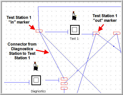
Figure 7.12: Station markers and route connections
If you miss a connection, you just will not see the part moving between the associated stations. To connect existing station markers, click on the Route button. The cursor will turn into a cross-hair and you can select the appropriate station markers. Notice that the station marker will become highlighted as you connect. If you do not have existing station markers, after clicking the Route button your first click will lay down a station marker and then you move your cursor to the location for the second station marker. This process takes a little patience and practice. If you are having trouble selecting stations etc. you should consider using the View toolbar to zoom in to help with the process. In addition, if you have to repeat the same step over and over, you can right-click on the mouse after a step (e.g. placing a station marker) and choose the Repeat Last Action item from the pop up menu. By using this, you do not have to repeatedly press the toolbar button.
If you run the model with the animation on, you will see the parts moving along the route connectors between the stations, the resource states changing, and the queues increasing and decreasing. If you watch the animation carefully, you should notice that the repair workers become busy when either working on a part or transporting the part. As previously mentioned, it would be nice to separate that out in the animation. It can be done, but the STATESET module would need to be used for the resources. You should consult the Users Guide or help system for more information on the STATESET module.
Having the workers both tend to the processing on the machines and move the parts between the stations has caused the system time to increase. The next section examines the use of dedicated workers to transport the parts between stations using the TRANSPORTER module.