6.6 Miscellaneous Modeling Concepts
This section discusses a number of additional constructs available within that facilitate common modeling situations that have not been previously described. The first topic allows for finer control of the routing of entities to stations for processing. The second situation involves improving the scalability of your models by making stations generic. Lastly, the use of the active entity to pick up and drop off other entities will be presented. This allows for another way to form groups of entities that travel together that is different than the functionality available in the BATCH module.
6.6.1 Picking Between Stations
Imagine that you have just finished your grocery shopping and that you are heading towards the check-out area. You look ahead and scan the checkout stations in order to pick what you think will be the line that will get your check out process completed the fastest. This is a very common situation in many modeling instances: the entity is faced with selecting from a number of available stations based on the state of the system. While this situation can be handled with the use of DECIDE modules, the implementation of many criteria to check can be tedious (and error prone). In addition, there are often a set of common criteria to check (e.g. shortest line, least busy resource, etc.). Because of this has available the PICKSTATION module on the Advanced Transfer panel. The PICKSTATION module combines the ability to check conditions prior to transferring the entity out of a station.
SMARTS file, Smarts113.doe, represents a good example for this situation In the model, entities are created according to a Poisson process with a rate of 1 every minute. The arriving entities then must choose between two stations for service. In this case, their choice should be based on the number of entities en route to the stations and the current number of entities waiting at the stations. After receiving processing at the stations, the entities then depart the system.
As can be seen in Figure 6.66, the entity is created and then immediately enters the Entry station. From the Entry station, the entity will be routed via the PICKSTATION module to one of the two processing stations. The processing is modeled with the classic SEIZE, DELAY, RELEASE logic. After the processing, the entity is routed to the Later (exit) station where it is disposed. The only new modeling construct required for this situation is the PICKSTATION module.
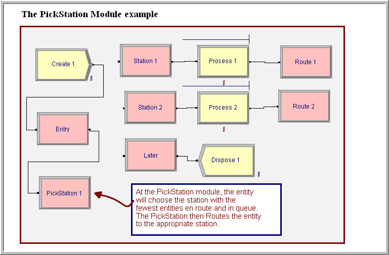
Figure 6.66: Overview of PICKSTATION example
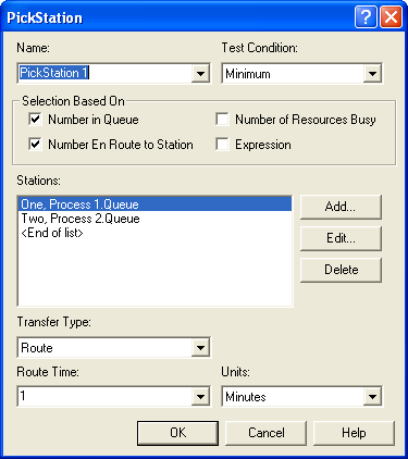
Figure 6.67: PICKSTATION module
The PICKSTATION module is very similar to a ROUTE module as shown in Figure 6.67. The top portion of the module defines the criteria by which the stations will be selected. The bottom portion of the module defines the transfer out mechanism. In the figure, the module has been set to select based on the minimum of the number in queue and the number en route to the station. The Test Condition field allows the user to pick according to the minimum or the maximum. The Selection Based On section specifies the constructs that will be included in the selection criterion. The user must provide the list of stations and the relevant construct to test at each station (e.g. the process queue). The selection of the construct is dependent on criteria that were selected in the Selection Based On area.
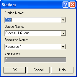
Figure 6.68: Adding a station to the PICKSTATION module
Figure 6.68 illustrates the dialog box for adding a station to the list when all criteria have been selected. Notice that the specification is based on the station. In the figure, the user can select the station, a queue at the station, a resource at the station or a general expression to be evaluated based on the station. scans the list to find the station that has the minimum (or maximum) according to the criteria selected. In the case of ties, will pick the station that is listed first according the Stations list. After the station has been selected, the entity will be routed according to the standard route options (transport, route, convey, and connect). In the case of the connect option, the user is given the option to save the picked station in an attribute, which can then be used to specify the station in a transfer module (e.g. CONVEY). In addition, since the choice of transport or convey requires that the entity has control over a transporter or has accessed the conveyor, the entity must first have used the proper modules to gain control of the material handling construct (e.g. REQUEST) prior to entering the PICKSTATION.
As you can see, the specification and operation of the PICKSTATION module is relatively straight forward. The only difficulty lies in properly using the Expression option.
Let’s consider a modification to the example to illustrate the use of an expression. Let’s suppose that the two resources within the example follow a schedule such that every hour the resources take a 10 minute break, with the first resource taking the break at the beginning of the hour and the second resource taking a break at the middle of the hour. This ensures that both resources are not on break at the same time. In this situation, arriving customers would not want to choose the station with the resource on break; however, if the station is picked based solely on the number in queue and the number en route, the entities may be sent to the station on break. This is because the number in queue and the number en route will be small (if not zero) when the resource is on break. Therefore some way is needed to ensure that the station on break is not chosen during the break time. This can be done by testing to see if the resource is inactive. If it is inactive, the criteria can be multiplied by a large number so that it will not be chosen.
To implement this idea, two schedules were created, one for each resource to follow. Figure 6.69 shows the two schedules. In the schedule for resource 1, the capacity is 0 for the first 10 minutes and is then 1 for the last 50 minutes of the hour. The schedule then repeats. For the second resource’s schedule, the resource is available for 30 minutes and then the break starts and lasts for 10 minutes. The resource is then available for the rest of the hour. This allows the schedule to repeat hourly.
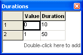
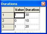
Figure 6.69: Schedules for PICKSTATION extension for resource 1 and 2
Now the PICKSTATION module needs to be adjusted so that the entity does
not pick the station with the resource that is on break. This
implementation can be accomplished with the expression: (STATE(resource name) == INACTIVE_RES)*vBigNumber. In this case, if the named
resource’s state is inactive the Boolean expression yields a 1 for true.
Then the 1 is multiplied by a big number (e.g. 10000), which would yield
the value 10000 if the state is inactive. Since the station with minimum
criteria is to be selected, this will penalize any station that is
currently inactive. The implementation of this in the PICKSTATION module
is shown in Figure 6.70. If you run the model,
Smarts113-PickStation-ResourceStaffing.doe, that accompanies this
chapter, you can see that the entity does not pick the station that is
on break.
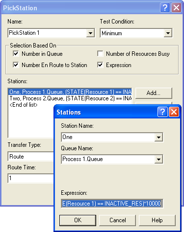
Figure 6.70: Preventing a station from being chosen while inactive
In many models (including this one), the station logic is essentially the same, SEIZE, DELAY, RELEASE. The next section considers the possibility of replacing many stations with a generic station that can handle any entity intended for a number of stations.
6.6.2 Generic Station Modeling
A generic station is a station (and its accompanying modules) that can handle the processing for any number of designated stations. To accomplish this, sets must be used to their fullest. Generic stations allow a series of commonly repeating modules to be replaced by a set of modules, sort of like a subroutine. However, the analogy to subroutines is not very good because of the way Arena handles variables and attributes. The trick to converting a series of modules to using generic stations is to properly index into sets. An example is probably the best way to demonstrate this idea.
Let’s reconsider the test and repair shop from Chapter 4 and shown in Figure 6.71. Notice that the three testing stations in the middle of the model all have the same structure. In fact, the only difference between them is that the processing occurs at different stations. In addition, the parts are routed via sequences and have their processing times assigned within the SEQUENCE module. These two facts will make it very easy to replace those 9 modules with 4 modules that can handle any part intended for any of the test stations.
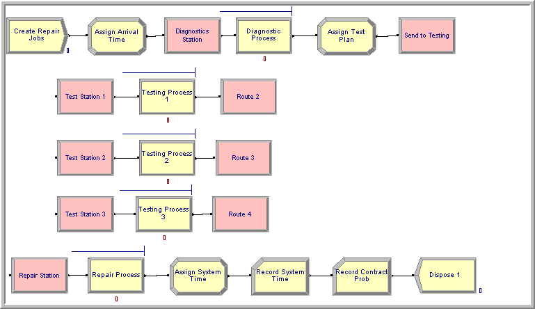
Figure 6.71: Overview of test and repair model
Figure 6.72 show the generic version of the test and repair model. As shown in the figure, the testing stations have been replaced by the station name Generic Station. Notice that the generic modeling is: STATION, SEIZE, DELAY, RELEASE, ROUTE. The real trick of this model begins with set modeling.
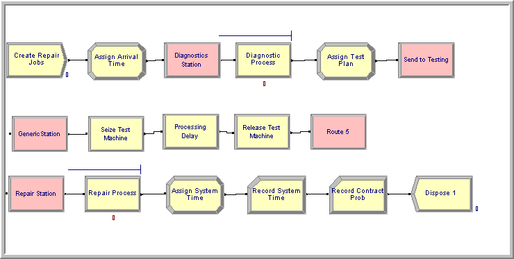
Figure 6.72: Generic station version of test and repair model
Three sets must be defined for this model: a set to hold the test stations, a set to hold the test machine resources, and a set to hold the processing queues for the test machines.
There are two ways to define a set of stations: 1) using the Advanced Set module or 2) using the set option within the STATION module. Since a generic station is being built, it is a bit more convenient to use the set option within the STATION module.
Figure 6.73 illustrates the generic station module. Notice how the station type field has been specified as “Set.” This allows a set to be defined to hold the stations to be represented by this station set. The station set members for the test stations have all been added. will use this one module to handle any entity that is transferred to any of the listed stations. A very important issue in this modeling is the order of the stations listed. In the other sets that will be used, you need to make sure that the resources and queues associated with the stations are listed in the same order.
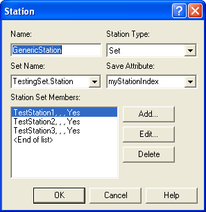
Figure 6.73: Generic station module with set option
When an entity is sent to one of the stations listed, which station the generic station is currently representing must be known. This is accomplished with the Save Attribute. The saved attribute will record the index of the station in its set. That’s important enough to repeat. It does not hold the station selected. It holds the index for the station in the station set. This index can be used to reference into a queue set and a resource set to make the processing generic. Figure 6.74 illustrates the resource and queue sets needed for the model. The resource set is defined using the SET module on the Basic Process panel, and the queue set is defined using the Advanced SET module on the Advanced Process panel. With these sets defined, they can be used in the SEIZE and RELEASE modules.
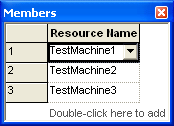
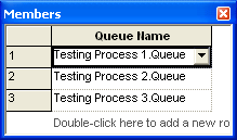
Figure 6.74: Resource and queue sets for generic station modeling
In the original model, a PROCESS module was used to represent the testing processes. In this generic model, the PROCESS module will be replaced with the SEIZE, DELAY, and RELEASE modules from the Advanced Process panel. The primary reason for doing this is so that the queue set can be accessed when seizing the resource.
Figure 6.75 illustrates the SEIZE module for the
generic test and repair model. When seizing the resource the set option
has been used by selecting a specific member from the TestMachineSet
as specified by the myStationIndex. Thus, if the entity had been sent
to the test station 2, the myStationIndex would have the value 2. This
value is then used as the index into the TestMachineSet. Now you
should see why the order of the sets matters. In addition, if the entity
must wait for the resource it needs to know which queue to wait in. The
SEIZE module has an option to allow the queue to be selected from a set.
In this case, the TestMachineQSet can be accessed by using the
myStationIndex. Since there are multiple queues being handled by this
one SEIZE module takes away the default queue animation. You can add
back the animation queues using the Animate toolbar when you develop an
animation for your model.
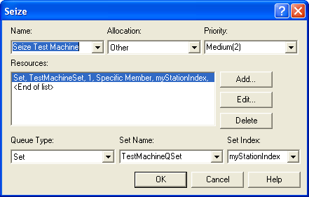
Figure 6.75: SEIZE module for generic station model
The DELAY module for the generic station is shown in
Figure 6.76. It is simple to make generic because
the SEQUENCE module is being used to assign to the myTestingTime
attribute when the entity is routed to the station.
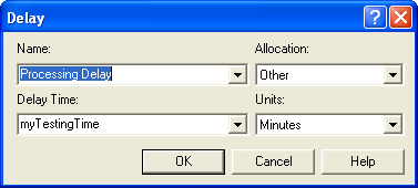
Figure 6.76: DELAY module for generic station model
The RELEASE module for the generic station is shown in
Figure 6.77. In this case, the set option has
been used to specify which resource to release. The myStationIndex is
used to index into the TestMachineSet to release a specific member.
The ROUTE module is just like the ROUTE module used in the original test
and repair model. It routes the part using the sequence option.
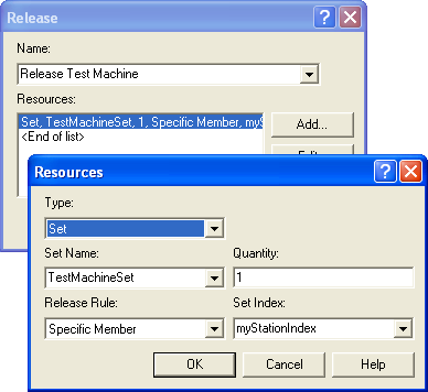
Figure 6.77: RELEASE module for generic station model
If you run this model, found in the file GenericRepairShop.doe, the results will be exactly as seen in Chapter 4. Now, you might be asking yourself: “This generic stuff seems like a lot of work. Is it worth it?” Well, in this case 4 flow chart modules were saved (5 in the generic versus 9 in the original model). Plus, three additional sets were added in the generic model. This doesn’t seem like much of a savings. Now, imagine a realistically sized model with many more test stations, e.g. 10 or more. In the original model, to add more testing stations you could cut and paste the STATION, PROCESS, ROUTE combination as many times as needed, updating the modules accordingly. In the generic model, all that is needed is to add more members to the sets. You would not need to change the flow chart modules. All the changes that would need to take place to run a bigger model would be in data modules (e.g. sets, sequences, etc). This can be a big advantage when experimenting and running different model configurations. The generic model will be much more scalable.
Until you feel comfortable with generic modeling, I recommend the following. First, you should develop the model without the generic modeling. Once the model has been tested and is working as you intended, then look for opportunities to make the model generic. Consider making it generic if you think you can take advantage of the generic components during experimentation and if you think reuse of the model is an important aspect of the modeling effort. If the model is only going to be used once to answer a specific question, then you probably don’t need to consider generic modeling. Even in the case of a one time model, if the model is very large, replacing parts of it with generic components can be a real benefit when working with the model. In this simple example, the generic modeling was easy because of the structure of the model. This will not always be the case. Thus, generic modeling will often require more thinking and adjustments than illustrated in this example; however, I have found it very useful in my modeling.
6.6.3 Picking up and Dropping Off Entities
In many situations, entities must be synchronized so that they flow together within the system. Chapter 4 presented how the BATCH and SEPARATE modules can be used to handle these types of situations. Recall that the BATCH module allows entities to wait in queue until the number of desired entities enter the BATCH module. Once the batch is formed, a single representative entity leaves the BATCH module. The batch representative entity can be either permanent or temporary. In the case of a temporary entity, the SEPARATE module is used to split the representative entity into its constituent parts.
What exactly is a representative entity? The representative entity is an entity created to hold the entities that form the batch in an entity group. An entity group is simply a list of entities that have been attached to a representative entity. The BATCH module is not the only way to form entity groups. In the case of a BATCH module, a new entity is created to hold the group. The newly created entity serves as the representative entity. In contrast, the PICKUP module causes the active entity (the one passing through the PICKUP module) to add entities from a queue to its entity group, thereby becoming a representative entity.
To get entities out of the entity group, the DROPOFF module can be used. When the active entity passes through the DROPOFF module, the user can specify which entities in the group are to be removed (dropped off) from the group. Since the entities are being removed from the group, the user must also specify where to send the entities once they have been removed. Since the entities that are dropped off were represented in the model by the active entity holding their group, the user can also specify how to handle the updating/specification of the attributes of the dropped off entities.
The PICKUP and DROPOFF modules are found on the Advanced Process Panel.
Figure 6.78, 6.79, 6.80 illustrate the PICKUP and DROPOFF modules.
In the PICKUP module, the quantity field specifies how many entities to
remove from the specified queue starting at the given rank. For example,
to pick up all the entities in the queue, you can use NQ(queue name) in
the quantity field.
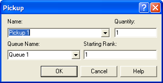
Figure 6.78: The PICKUP module
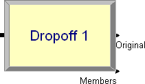
Figure 6.79: The DROPOFF module
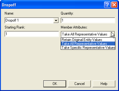
Figure 6.80: The DROPOFF module dialog
The number of entities picked up cannot be more than the number of entities in the queue or a run time error will result. Thus, it is very common to place a DECIDE module in front of the PICKUP module to check how many entities are in the queue. This is very useful when picking up 1 entity at a time. When an entity is picked up from the specified queue, it is added to the group of the entity executing the PICKUP module. The entities that are picked up are added to the end of the list representing the group.
Since entities can hold other entities within a group, you may need to get access to the entities within the group during model execution. There are a number of special purpose functions/variables that facilitate working with entity groups. From the help system information on the following functions is available:
- AG(Rank, Attribute Number)
AG returns the value of general-purpose attribute Attribute Number of the entity at the specified Rank in the active entity’s group. The function NSYM may be used to translate an attribute name into the desired Attribute Number.
- ENTINGROUP(Rank
[, Entity Number]) ENTINGROUP returns the entity number (i.e., IDENT value) of the entity at the specified Rank in the group of entity representative Entity Number.
- GRPTYPE(Entity Number)
When referencing the representative of a group formed at a BATCH module, GrpType returns 1 if it is a temporary group and 2 if it is a permanent group. If there is no group, then a 0 will be returned.
- ISG(Rank)
This function returns the special-purpose jobstep (Entity.Jobstep, or IS) attribute value of the entity at the specified Rank of the active entity’s group.
- MG(Rank)
This function returns the special-purpose station (Entity.Station, or M) attribute value of the entity at the specified Rank of the active entity’s group.
- NSG(Rank)
This function returns the special-purpose sequence (Entity.Sequence, or NS) attribute value of the entity at the specified Rank of the active entity’s group.
- NG(Entity Number)
NG returns the number of entities in the group of representative Entity Number. If Entity Number is defaulted, NG returns the size of the active entity’s group.
- SAG(Attribute Number)
SAG adds the values of the specified Attribute Number of all members of the active entity’s group. The data type of the specified attribute must be numeric. The function NSYM may be used to translate an attribute name into the desired Attribute Number.
Notice that many of the functions require the rank of the entity in the
group. That is, the location in the list holding the group of entities.
For example, AG(1, NSYM(myArrivalTime)) returns the value of the
attribute named myArrivalTime for the first entity in the group. Often
a SEARCH module is used to search the group to find the index of the
required entity.
The DROPOFF module is the counterpart to the PICKUP module. The DROPOFF
module removes the quantity of entities starting at the provided rank
from the entity’s group. The original entity exits the exit point
labeled Original. Any members dropped off exit the module through the
point labeled Members. If there are no members in the group, then the
original simply exits. Note that, similar to the case of SEPARATE, you
can specify how the entities being dropped will handle their attributes.
The option to Take Specific Representative Values causes an additional
dialog box to become available that allows the user to specify which
attributes the entities will get from the representative entity. The
functions discussed earlier can be used on the members of the group to
find the rank of specific members to be dropped off. Thus, entities can
be dropped off singly or in the quantity specified. The representative
entity will continue to hold the other members in the group. The special
variable NG is very useful in determining how many entities are in the
group. Again, the SEARCH module can be useful to search the group to
find the rank of the entities that need to be dropped off.
To illustrate the PICKUP and DROPOFF modules, the modeling of a simple shuttle bus system will be examined. In this system, there are two bus stops and one bus. Passengers arrive to bus stop 1 according to a Poisson arrival process with a mean rate of 6 per hour. Passengers arrive to bus stop 2 according to a Poisson arrival process with a mean rate of 10 per hour. Passengers arriving at bus stop 1 desire to go to bus stop 2, and passengers arriving to bus stop 2 desire to go to bus stop 1. The shuttle bus has 10 seats. When the bus arrives to a stop, it first drops off all passengers for the stop. The passenger disembarking time is distributed according to a lognormal distribution with a mean of 8 seconds and a standard deviation of 2 seconds per passenger. After all the passengers have disembarked, the passengers waiting at the stop begin the boarding process. The per passenger boarding time (getting on the bus and sitting down) is distributed according to a lognormal distribution with a mean of 12 seconds and a standard deviation of 3 seconds. Any passengers that cannot get on the bus remain at the stop until the next bus arrival. After the bus has completed the unloading and loading of the passengers, it travels to the next bus stop. The travel time between bus stops is distributed according to a triangular distribution with parameters (16, 20, 24) in minutes. This system should be simulated for 8 hours of operation to estimate the average waiting time of the passengers, the average system time of the passengers, and the average number of passengers left at the stop because the bus was full.
Upon first analysis of this situation, it might appear that the way to model this situation is with a transporter to model the bus; however, the mechanism for dispatching transporters does not facilitate the modeling of a bus route. In standard transporter modeling, the transporter is requested by an entity. As you know, most bus systems do not have the passengers request a bus pick up. Instead, the bus driver drives the bus along its route stopping at the bus stops to pick up and drop off passengers. The trick to modeling this system is to model the bus as an entity. The bus entity will execute the PICKUP and DROPOFF modules. The passengers will also be modeled as entities. This will allow the tabulation of the system time for the passengers. In addition, since the passengers are entities, a HOLD module with an infinite hold option can be used to model the bus stops. That is really all there is to it! Actually, since the logic that occurs at each bus stop is the same, the bus stops can also be modeled using generic stations. Let’s start with the modeling of the passengers.
Figure 6.81 presents an overview of the bus system model. The entire model can be found in the file BusSystem.doe associated with this chapter. In the figure, the top six modules represent the arrival of the passengers. The pseudo-code is straightforward:
CREATE passenger with time between arrivals exponential with mean 10 minutes
ASSIGN arrival time
HOLD until removed
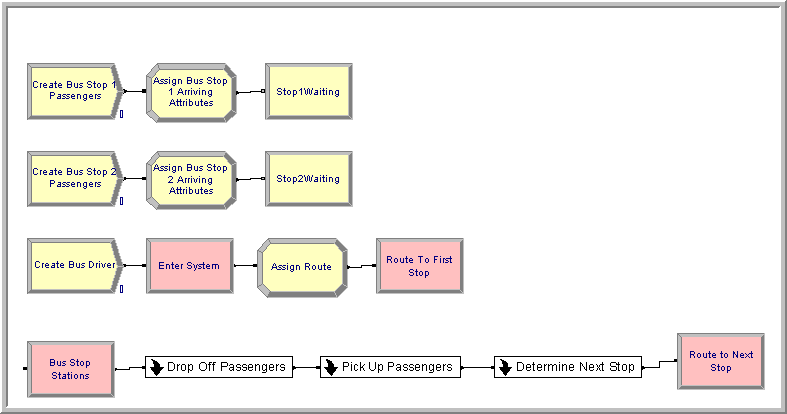
Figure 6.81: Overview of the bus system model
The next four modules in
Figure 6.81 represent the creation of the bus. The
bus entity is created at time zero and assigned the sequence that
represents the bus route. A sequence module was used called BusRoute.
It has two job steps representing the bus stops, BusStation1 and
`BusStation2’. Then the bus is routed using a ROUTE module according to
the By Sequence option. Since these are all modules that have been
previously covered, all the details will not be presented; however, the
completed dialogs can be found in the accompanying model file. Now let’s
discuss the details of the bus station modeling.
As previously mentioned, a generic station can be used to represent each
bus stop. Figure 6.82 shows the generic station for the
bus stops. The station type has been defined as "Set" and the stations
representing the bus stops, BusStation1 and BusStation2 have been
added to the station set. The key to the generic modeling will be the
attribute, myBusStop, which will hold the index of the current
station. In Figure 6.81, three sub-models have been used to
represent the drop off logic, the pick up logic, and the logic to decide
on the next bus stop to visit.
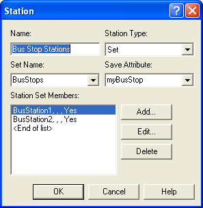
Figure 6.82: Generic station for bus stops
The logic for dropping off passengers is shown in Figure 6.83. This is a perfect place to utilize the WHILE-ENDWHILE blocks. Since the variable NG represents the number of entities in the active entity’s group, it can be used in the logic test to decide whether to continue to drop-off entities. This works especially well in this case since all the entities in the group will be dropped off. If the active entity (bus) has picked up any entities (passengers), then NG will be greater than zero and the statements in the while construct will be executed. The bus experiences a DELAY to represent the disembarking time of the passenger and then the DROPOFF module, see Figure 6.84, is executed. Notice that in this case, since the system time of the passengers must be captured, the Retain Original Entity Values option should be used.
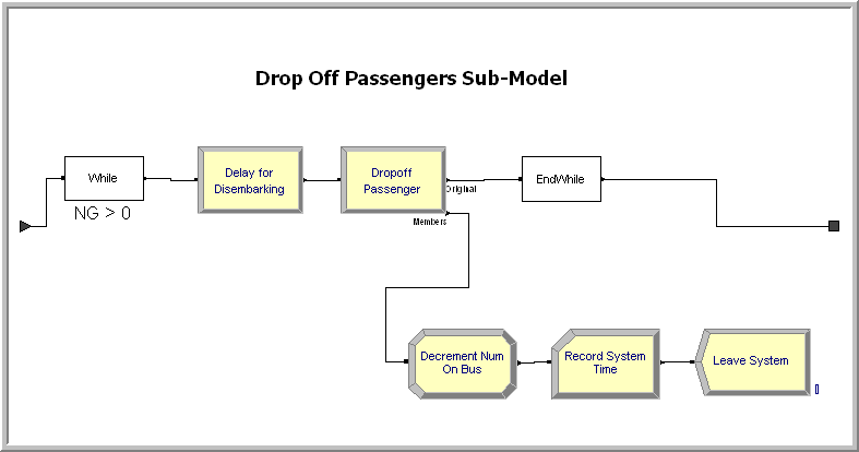
Figure 6.83: Dropping off passengers sub-model
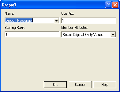
Figure 6.84: DROPOFF module for passengers
The details of the rest of the modules can be found in the accompanying model file. In the case of a bus system with more stops, logic would be needed to search the group for passengers that want to get off at the current stop. The reader will be asked to explore this idea in the exercises.
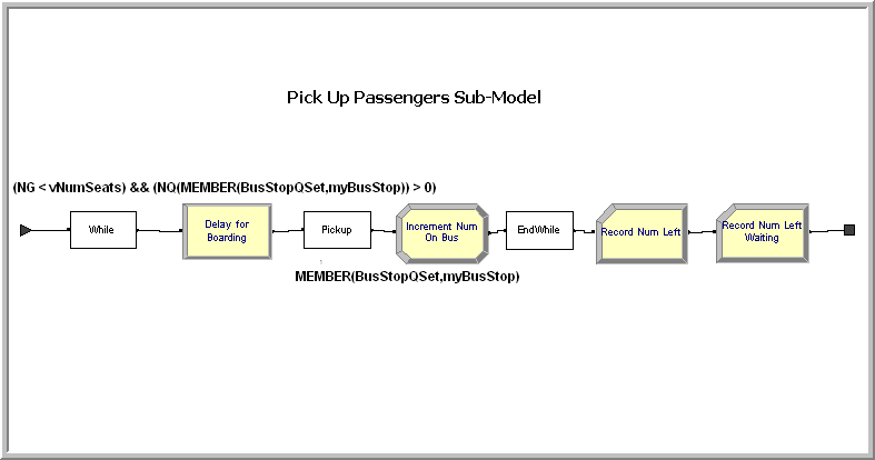
Figure 6.85: Picking up passengers sub-model
The logic to pick up passengers is very similar to the logic for dropping off the passengers. In this case, a WHILE-ENDWHILE construct will again be used, as shown in Figure 6.85; however, there are a couple of issues that need to be handled carefully in this sub-model.
In the drop-off passenger sub-model, the bus stop queues did not need to be accessed; however, when picking up the passengers, the passengers must be removed from the appropriate bus stop waiting queue. Let’s take a careful look at the logical test condition for the WHILE block:
(NG < vNumSeats) && (NQ(MEMBER(BusStopQSet,myBusStop)) > 0)
A variable, vNumSeats, has been defined which represents the capacity
of the bus. The special purpose group variable, NG, is compared to the
capacity, as long as NG is less than the capacity the next passenger
can be picked up from the bus stop queue. What about the second part of
the test? Recall that it is a logical error to try to pick up an entity
from an empty queue. Thus, the statement, NQ(queue name) > 0, tests to
see if the queue holds any entities. Since generic modeling is being
used here, the implementation must determine which queue to check based
on the bus stop that the bus is currently serving. A Queue Set called
BusStopQSet has been defined to hold the bus stop waiting queues. The
queues have been added to this set in the same order as the bus stop
stations were added to the bus stop station set. This ensures that the
index into the set will return the queue for the appropriate station.
The function, MEMBER(set name, index) returns the member of the set for
the supplied index. Thus, in the case of
MEMBER(BusStopQSet,myBusStop), the queue for the current bus stop will
be returned. In this case, both NG and NQ need to be checked so that
passengers are picked up as long as there are waiting passengers and the
bus has not reached its capacity. If a passenger can be picked up, the
bus delays for the boarding time of the passenger and then the PICKUP
block is used to pick up the passenger from the appropriate queue. The
PICKUP block, shown in
Figure 6.86, is essentially the same as the PICKUP
module from the Advanced Process panel; however, with one important
exception. The PICKUP block allows an expression to be supplied in the
Queue ID dialog field that evaluates to a queue. The PICKUP module from
the Advance Process panel does not allow this functionality, which is
critical for the generic modeling.
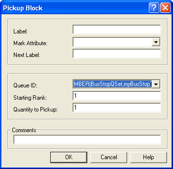
Figure 6.86: The PICKUP Block
In this situation, the MEMBER(BusStopQSet,myBusStop) is used to return
the proper queue in order to pick up the passengers. Each time the
PICKUP block is executed, it removes the first passenger in the queue.
After the passengers are picked up at the stop, the logic to record the
number left waiting is executed. In this case, a snap shot view of the
queue at this particular moment in time is required. This is an
observation based statistic on the number in queue.
Figure 6.87 shows the appropriate RECORD module. In this
case, a tally set can be used so that the statistics can be collected by
bus stop. The expression to be observed is:
NQ(MEMBER(BusStopQSet,myBusStop)).
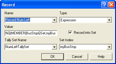
Figure 6.87: Recording the number of passengers not picked up
Running the model for 10 replications of 8 hours yields the results shown in Figure 6.88. Notice that the waiting time for the passengers is a little over 20 minutes for the two queues. In addition, the results indicate that on average, there is less than one passenger left waiting because the bus is full. The reader will be asked to explore this model further in the exercises.
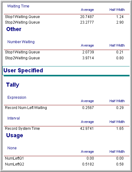
Figure 6.88: Results for the bus system model
Based on this example, modeling with the PICKUP and DROPOFF modules is not too difficult. The additional functions, e.g. AG() etc., which have been not illustrated, are especially useful when implementing more complicated decision logic that can select specific entities to be picked up or dropped off. In addition, with the generic representation for the bus system, it should be clear that adding additional bus stops can be readily accomplished.
The coverage of the major modeling constructs within Arena has been completed. The next section summarizes this chapter.