2.8 Animating the Drive Through Pharmacy Model
While running the pharmacy model with the animation on, you saw some of Arena’s basic animation capabilities. Positioned over the PROCESS module is an animation queue, which shows the cars that are waiting for the pharmacist. has many other animation features that can be added to a model. Animation is important for helping to verify that the model is working as intended and for validating the model’s representation of the real system. This section will illustrate a few of Arena’s simpler animation features by having you augment the basic pharmacy model. In particular, you will change the entity picture from a van to a car, draw the pharmacy building, and show the state of the pharmacist (idle or busy). You will also animate the number of cars waiting in the line (both visually and numerically).
When defining the entity type, a picture of a van was originally
selected for the entity. has a number of other predefined graphical
pictures that can be used within the model. The available entity
pictures can be found from the Edit menu as shown in
Figure 2.47. You can select different picture files by navigating to where they are installed within your Arena installation. See Figure 2.48 This may vary by installation. For example, the picture library can be found at the following location in my installation C:\Users\Public\Documents\Rockwell Software\Arena\PictureLibraries.
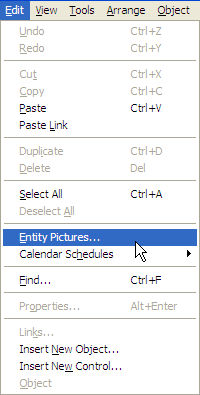
Figure 2.47: Accessing entity pictures
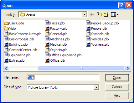
Figure 2.48: Entity pictures folder
Once you have selected Edit \(>\) Entity Pictures, you should see the entity picture placement dialog as shown in Figure 2.49. The entity picture placement dialog is divided into two functions: the picture list (on the left of dialog) and the picture library (on the right of the dialog). The picture list represents the entity pictures that are listed in the ENTITY module. If you scroll down you will find the picture of the van in the list. By navigating to the picture libraries within the distribution folder on your hard-drive (see Figure 2.48 you can select the Vehicles.plb file. When selected as the current library, your entity picture placement dialog should look as shown in Figure 2.49.
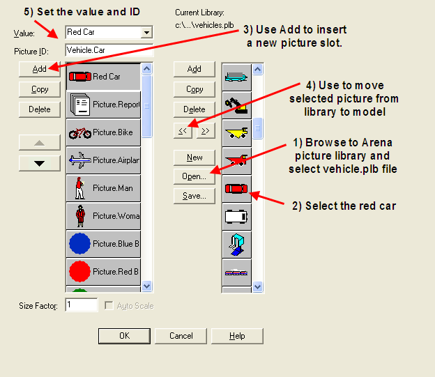
Figure 2.49: Entity picture placement dialog
Scroll down in the vehicle library and select the red car, then select the “\(<<\)” button to move the picture to the picture list. Finally, you should give the picture a name in the list (e.g. Red Car). Now, go back to the ENTITY module and associate the picture with your entity. At the time of this writing, the name does not appear on the Entity module drop down list, but the picture is available. Just type in the correct name in the Entity module to have the entity picture represented by the red car.
Now, you will use Arena’s drawing tools to draw the outline of the pharmacy building. has standard drawing tools (e.g. lines, rectangles, polygons, etc) as well as way to add text, fill options etc. These tools are available through the Drawing toolbar as shown in Figure 2.50. You can also turn on the drawing grid and the ruler, which are useful in placing the drawing objects. In this situation, drawing will be kept to a rather simple/crude representation of the pharmacy. Essentially, the pharmacy will be represented as a box, the drive through lane as a line with the road line pattern, and the pass through service window as two lines with 3pt thickness.
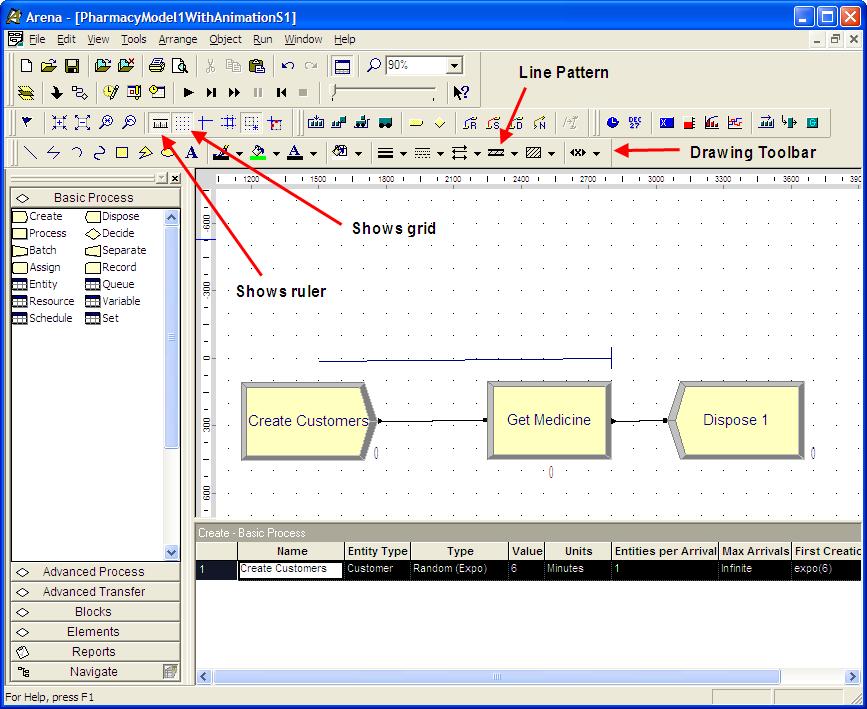
Figure 2.50: Basic drawing toolbar
Figure 2.51 illustrates the background drawing for the pharmacy. The drawing editor works like most computer based drawing editors. You should just drag and drop the items, set the fill options, thickness, and line pattern as you go. This portion of this example is available in the PharmacyModelWithAnimationS1.doe file.
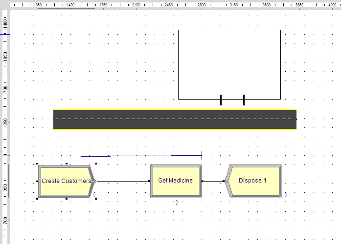
Figure 2.51: Simple pharmacy drawing within Arena model Window
In the next part of the example, you will animate the resource so that you can see when the pharmacist is busy or idle, provide a location to show the customer currently being served, and better represent the waiting cars in the drawing.
Within a resource can be in one of four default states (idle, busy, inactive, and failed). The inactive and failed states will be discussed later in the text. The idle state represents the situation that at least 1 unit of the resource is available. In the pharmacy model, there is only 1 pharmacist, so if the pharmacist is not serving the customer, the pharmacist is considered idle. The busy state represents the situation where all available units of the resource are currently seized. In the case of the pharmacy model, since there is only 1 resource unit (the pharmacist), the resource is busy when the sole pharmacist is seized. In the animation, you will visibly represent the state of the pharmacist. This can be done through Arena’s animate toolbar and in particular the animate resource button.
Click the Resource button on the Animate toolbar.
The Resource Placement dialog box appears. Use the open button to navigate to the people.plb picture library.
Select the over head person view picture from the library’s list of pictures, see Figure 2.52 Then, select the Copy button. This will cause a copy of the picture to be made in the library.
After copying the picture, double-click on the picture. This will put you in the resource editor. This is like a drawing editor. For simplicity, just select the picture and change the fill color to green. If you want to make it look just like the picture in the text, you need to un-group the picture elements and change their appearance as necessary.
Assign the white over head person view picture to the idle state and the green picture that was just made to the busy state. To change the idle picture: Click the Idle button in the table on the left. Select from the picture library table on the right the picture of the white over head view person picture. Click the Transfer button between the tables to use the picture for the Idle resource state. To change the busy picture: Click the Busy button in the table on the left. Select from the picture library table on the right the picture of green worker that was just made. Click the Transfer button between the tables to use the selected picture when the pharmacist is busy.
Now you need to rotate the picture so that the person is facing down. Double-click on the new Idle resource picture to open the resource editor. Then, you should select the whole picture and choose Arrange \(>\) Rotate in order to rotate the picture so that the pharmacist is facing down. Close the editor and do this for the Busy state also.
Click on the Seize Area check box. This will be discussed shortly.
Click OK to close the dialog box. (All other fields can be left with their default values.) will ask about whether you want to save the changes to picture library. If you want to keep the green over head view person for use in later models, answer yes during the saving process. The cursor will appear as a cross hair. Move it to the model window and click to place the pharmacist resource animation picture within the pharmacy.
Now that the pharmacist is placed in the pharmacy, it would be nice to show the pharmacist serving the current customer. This can be done by using the seize area for a resource. The seize area animates the entities that have seized the resource. By default the seize area is not shown on the animation of a resource. The checking of the Seize Area check box allows the seize area to be visible. After placing the resource, zoom in on the resource and notice a small double circle. This is the seize area. Select the seize area and drag it so that it is positioned in the road adjacent to the pharmacy.
Now, you need to place the queue of waiting cars on the road. Select the animation queue on top of the Get Medicine PROCESS module and delete it. Now, go to the Queue button on the Animate toolbar and select it. This will allow you to create a new queue animation element that is not physically attached to the Get Medicine PROCESS module and place it in the road. Fill in the Queue animation dialog as shown in Figure 2.53. Once you press OK, the cursor will turn in to a cross-hair and allow you to place the animation queue.
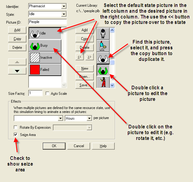
Figure 2.52: Resource animation state picture assignment
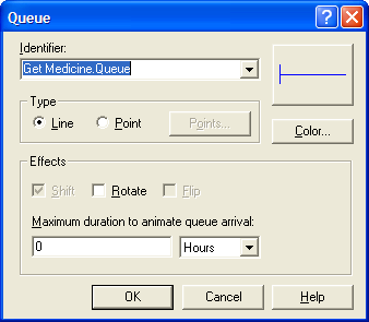
Figure 2.53: Queue animation dialog
The final piece of animation that you will perform is to show the current number of waiting cars within the pharmacy. Select the Variable button on the Animate toolbar and fill out the resulting dialog as per Figure 2.54. The cursor should turn to cross-hairs and you should place the variable animation inside the pharmacy as shown in Figure 2.55.
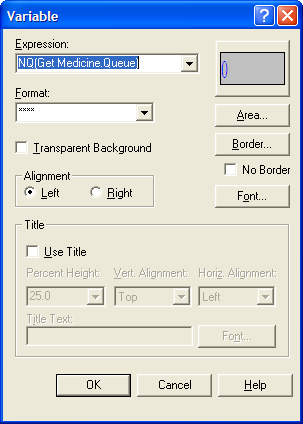
Figure 2.54: Variable animation dialog
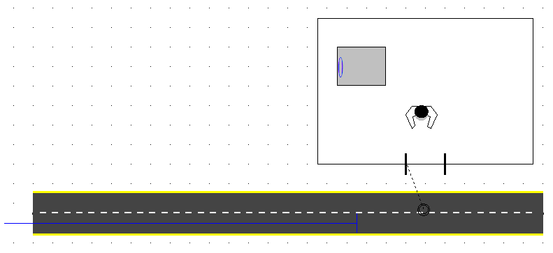
Figure 2.55: Final animation for pharmacy example
The last thing to do before running the animation will be to turn off the animation associated with the flow chart connectors. This will stop the animation of the customers within the flow chart modules and be less of a distraction. The Object menu contains the option to disable/enable the animation of the connectors as shown in Figure 2.56.
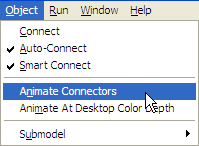
Figure 2.56: Disabling connector animation
The final version of the animated pharmacy model is available in the file, PharmacyModleWithAnimationS2.doe. If you run the model with the animation on, you will see the pharmacist indicated as busy or idle, the car currently in service, any cars lined up waiting, and the current number of cars waiting as part of the animation.
NR(resource name) variable, see Section 6.2, to show how many are busy (either numerically or with a level animation). Also, by showing the
seize point and adding multiple points you can show each entity as it is
using the resource. There is also something called a storage, see Section 4.1.4, which will do just about the same thing. You can also animate 1-D variable by
having the variable indicate whether each unit is busy or not. All of
these methods are illustrated in the attached Arena model. This should
approximate what you are trying to do. The variable method is probably
the best but takes the most work. If you are going to use the variable
method, then you might just look at using a resource set instead. If you
want to use a resource animation and show each separately, then you need
to define a different resource to represent each unit of the overall
resource, put them in a set and seize/delay/release from the set. Then,
you can animate each of the individual resources in the standard manner. Please see the Arena file, ResourceAnimations.doe that accompanies this chapter’s files for an example.
Animation is an important part of the simulation process. It is extremely useful for showing to decision makers and experts to explain and ensure that the model is accepted. With this example, you have actually learned a great deal about animating a model. One of the standard practices is to rely on the default animation that is available with the flow chart modules. Then, when animation is important for validation and for convincing decision makers, the simulation analyst can devote time to making the animation more worthy. Often, the animation is developed in one area of the model which can be easily accessed via the Navigate bar. Many detailed examples of what is possible with animation come as demo models with the distribution. For example, you should explore the models in the Examples folder (e.g. FlexibleManufacturing.doe). If you find that the drawing tools are limiting, then you can use other drawing programs to make the drawings and import them as background for your model. Arena also has the capability for developing 3D animation; however, this is not discussed in this text.
The first part of this text primarily uses the default animation that comes with the placement of flow chart modules and concentrates on the analysis of simulation models; however, Chapter 7 returns to more on the topic of animation, when material handling constructs (e.g. conveyors and transporters) are examined.