7.2 Constrained Transfer with Transporters
A transporter refers to one or more identical transfer devices that can be allocated to an entity for the purpose of transferring entities between stations. Two types of transporters are available:
- free path transporter
The travel time between stations depends on distance and speed.
- guided path transporter
The travel time between stations depends on distance and speed, and the movement of the transporter is restricted to a pre-defined network of intersections and links.
The standard delay option of the ROUTE or LEAVE modules assumes no resource constrained transfer. As indicated in the last section, the situation of a general resource being used for the transfer can be easily modeled. In that situation, the time of the transfer was specified. In the case of transporters, resource constrained transfer is still being modeled, but in addition, the physical distance of the transfer must be modeled. In essence, rather than specifying a time to transfer, you must specify a velocity and a distance for the transfer. From the velocity and distance associated with the transfer, the time of the transfer can be computed. In these situations, the physical device and its movement (with or without the entity) through the system is of key interest within the modeling.
To model with transporters, provides the following modules on the Advanced Transfer Panel:
- ALLOCATE
Attempts to allocate a unit of the transporter to the entity. This is like a seize module when using resources. If the transporter is not immediately available for the request, the entity must wait in a queue. ALLOCATE only gives a unit of the transporter to the entity. It does not move the transporter to the entity’s location. It changes the status from idle to busy. This is useful when you want to perform other activities before or during the time the empty transporter is moved to the entity’s location.
- MOVE
Causes an allocated transporter to move to a particular location. The controlling entity is not moved during this process.
- REQUEST
Attempts to allocate a transporter and then move the transporter to the location of the requesting entity. REQUEST has the net effect of having an ALLOCATE followed by a MOVE module.
- TRANSPORT
Causes the entity to be transported to its destination. To contrast TRANSPORT and MOVE, MOVE is moving unloaded and TRANSPORT is moving loaded with the entity. The entity must have possession of the transporter unit. Before the transporter can be reallocated to another requesting entity the transporter must be de-allocated using the FREE module.
- FREE
Causes the entity to de-allocate the transporter. This is similar to releasing a resource.
- HALT
Causes the transporter to stop moving and become inactive. If the transporter is currently busy at the time when an entity enters the Halt module, the status of the transporter is considered busy and inactive until the entity that controls the transporter frees the unit. If the transporter is idle at the time when an entity halts the transporter, it is set to inactive immediately. This is useful in modeling breakdowns during movement. Once halted, the transporter can not be allocated until it has been activated.
- ACTIVATE
This module causes a halted transporter to become active so that it can then continue its use within the model. It increases the capacity of a previously halted transporter or a transporter that was initially inactive (as defined in the TRANSPORTER module). The transporter unit that is activated will reside at the station location at which it was halted until it is moved or requested by an entity. If an allocation request is pending for the transporter at the time the unit is activated, the requesting entity will gain control of the transporter immediately.
- TRANSPORTER
This data module allows the user to define the characteristics of the transport device e.g. number of transporter units, default velocity, initial location, etc. In addition, the DISTANCE module associated with the transporter must be specified.
- DISTANCE
This data module allows the user to define the distances (in a consistent unit of measure, e.g.meters) for all the possible moves that the transporter may make. The values for the distances must be non-negative integers. Thus, if the distance is given in decimals (e.g. 20.2 meters), the distance should either be rounded (e.g. 20 meters) or scaled to integers (202 decameters). In any case, the units of measure for the distances must be consistent. The DISTANCE module essentially creates a from/to matrix for the distances between stations. These are the traveling distances for the transporters not the entities and should include both loaded and empty moves. For n station locations, you will have to specify at most n(n-1) possible distances. The distances in the distance matrix do not have to by symmetrical. In addition, you do not need to specify a distance if it never occurs (either when the transporter is loaded or empty). If a distance is not given it is assumed to be zero. If the distance is symmetric, only one pair needs to be specified.
Figure 7.13 illustrates the general case of using a transporter and how it relates to the modules. Since transporters are used to move entities between two stations, two stations have been indicated in the figure. At the first station, the entity performs the standard SEIZE, DELAY, and RELEASE logic. Then, the entity attempts to allocate a unit of the transporter via the REQUEST module. Notice that there is a queue for waiting for the transporter to arrive. The REQUEST also causes the transporter to move to the entity’s location, as indicated with the travel time to origin activity. Then, a loading activity can occur. After the loading activity has completed, the entity experiences the delay for the transport to the desired location. As can be seen in the figure, the LEAVE module facilitates this modeling. Once the entity arrives at its destination station, there can be a delay for unloading the transfer devise and then the transporter is freed. As shown in the figure, conceptually, the HALT and ACTIVATE modules affect whether or not the transporter is available to be requested/allocated.
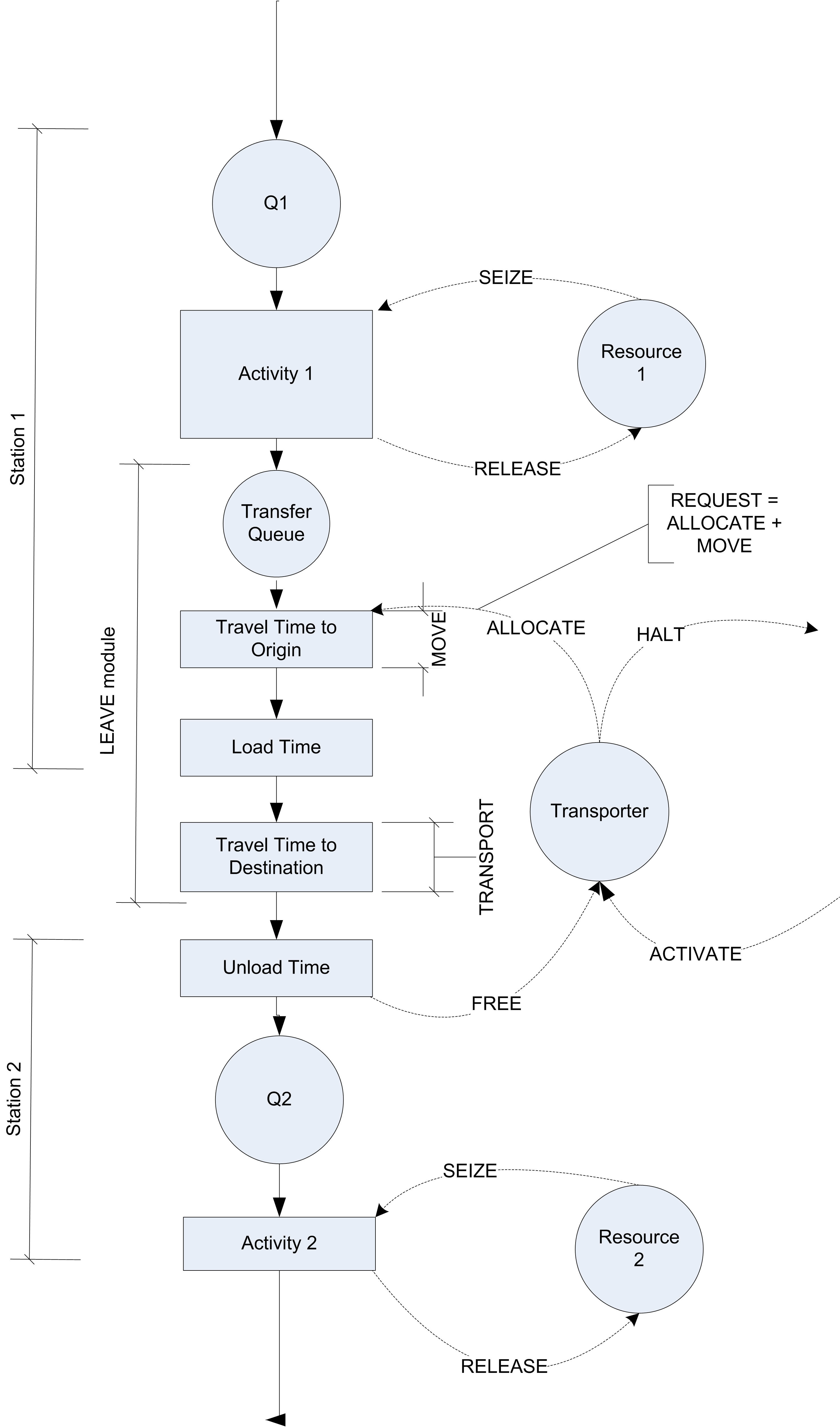
Figure 7.13: Activity diagram for general transporter case
The activity diagram in Figure 7.13 represents very well how the test and repair system will need to operate with transporters. The next section discusses how to use transporters to model the dedicated transport workers in the test and repair shop.
7.2.1 Test and Repair Shop with Workers as Transporters
The results of the constrained resource analysis indicated that modeling constrained transfer for the parts in the test and repair system can have a significant effect on the system’s ability to meet the contract requirements. This may be due to having the workers share the roles of tending the machines and transporting the parts. The following example investigates whether or not a set of dedicated workers would make sense for this system. In particular, the number of workers to dedicate to the transport task needs to be determined. Since there is a lot of walking involved, the model needs to be more precise in the physical modeling of the situation. This could also allow different layout configurations to be simulated if the relocation of the stations would make a difference in the efficiency of the system.
To model this situation using transporters, the distance between the
stations and a way to model the velocity of transport are required.
Since the workers have a natural variability in the speed of their
walking, a model for human walking speed is needed. Based on some time
study data, the velocity of a worker walking in the facility has been
determined to be distributed according to a triangular distribution with
a minimum of 22.86, a mode of 45.72, and a maximum of 52.5, all in
meters per minute. Since this distribution will be used in many
locations in the model, an EXPRESSION should be defined, called
eWalkingTimeCDF, which will be equal to TRIA(22.86, 45.72, 52.5).
Based on measuring the distance between the stations, the approximate distance between the stations has been determined as given in Table 7.3. Recall that both the loaded and unloaded distances for the transporter must be specified. For example, even though no parts are routed from repair to diagnostics, the distance from repair to diagnostics must be given because the worker (transporter) may be at the repair station when something needs to be moved from the diagnostic station. Thus, the worker must walk from the repair station to the diagnostic station (unloaded) in order to pick up the part. Notice also that the distances do not have to be symmetric (i.e. the distance from test 1 to test 2 does not have to be the same as the distance from test 2 to test 1).
| Station | Diagnostics | Test 1 | Test 2 | Test 3 | Repair |
|---|---|---|---|---|---|
| Diagnostics | – | 40 | 70 | 90 | 100 |
| Test 1 | 43 | – | 10 | 60 | 80 |
| Test 2 | 70 | 15 | – | 65 | 20 |
| Test 3 | 90 | 80 | 60 | – | 25 |
| Repair | 110 | 85 | 25 | 30 | – |
Starting with the finished model for the resource constrained example (without the animation) you can make small changes in order to utilize transporters. The first step is to define the distances. Figure 7.14 shows the DISTANCE module from the Advanced Transfer panel. The spreadsheet view allows an easier specification for the distances as shown in the figure. Multiple distance sets can be defined and used within the same model. The distance set must be given a name so that the name can be referenced by the TRANSPORTER module. Now, the transporters for the model can be defined using the TRANSPORTER module.
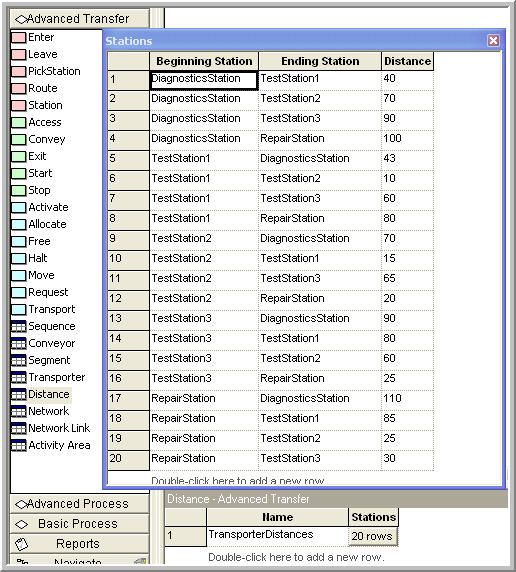
Figure 7.14: DISTANCE module for general transporter case
The TRANSPORTER module, see Figure 7.15, allows the transporter to be given a name and various other attributes. The TRANSPORTER module defines a fleet of identical mobile resources(e.g. vehicles). You can specify the number of units of the transporter. In this example, there will be 3 workers (all identical) that can transport the parts. The type of transporter in this case is Free Path and the Distance Set has been specified with the name used in the appropriate distance set from the DISTANCE module. The velocity within the TRANSPORTER module must be a real number (it cannot be an expression). The default value of the velocity will be used in the dialog because the velocity will be specified for each movement of the transporter within the model. The initial position specifies where the transporter will be located at the beginning of the replication. In this case, the workers will start active at the diagnostics station.
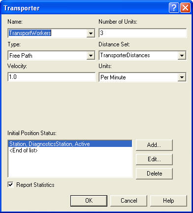
Figure 7.15: TRANSPORTER module for general transporter case
Now that the data modules are defined, let’s take a look at the overall model. Figure 7.16 shows the overall test and repair model after the modifications needed to use transporters. If you have the model open you should notice the new blue colored modules. These are from the Advanced Transfer panel and have replaced the LEAVE modules from the previous model.
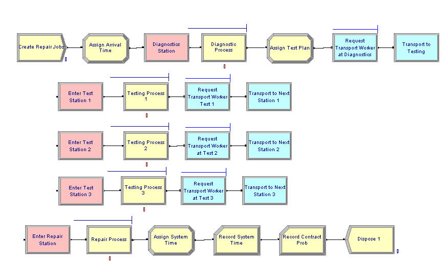
Figure 7.16: Overall test and repair model with transporters
The other change from the previous model involves the updating of the ENTER modules. The ENTER module change is very straight forward. You just need to specify that the type of transfer in option is Free Transporter and indicate what transporter to free. Figure 7.17 illustrates the changes to the ENTER module for entering test station 1. By default the transporter unit that the entity currently has is freed.
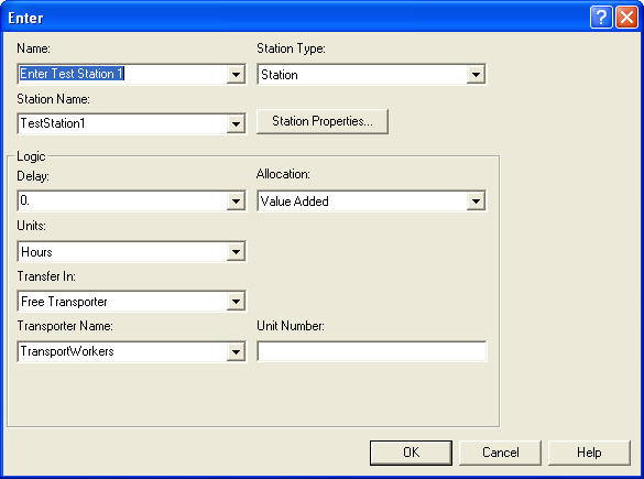
Figure 7.17: ENTER module with free transporter option
The changes to the LEAVE module are not as simple. Because a random velocity value is needed whenever the worker begins moving, the LEAVE module cannot be used. The LEAVE module relies on the default velocity for the transporter as defined in the TRANSPORTER module. Since the default velocity in the TRANSPORTER module must be a real number (not an expression), the REQUEST and TRANSPORT modules are used in this example.
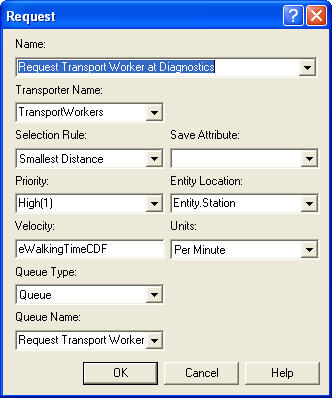
Figure 7.18: REQUEST module
Figure 7.18 shows the REQUEST module for the example. In the REQUEST module, you must specify which transporter to request and give the selection rule. The selection rules are the similar in concept to the selection rules for resources. The transporter selection rules are:
- Cyclical
cyclic priority selects the first available transporter beginning with the successor of the last transporter allocated (cycles through the transporters)
- Largest Distance
select the available transporter farthest from the requesting station
- Preferred Order
select the available transporter unit which has the lowest unit number
- Random
select randomly from the available transporter units
- Smallest Distance
select the nearest available transporter
- Specific Member
a specific unit of the transporter
- ER(Index)
select based on rule number Index defined in experiment frame
- UR(Index)
select transporter index UR, where UR is computed in a user coded function UR(LENT,NUR)
The selection rule is only used if one or more units of the transporter are available to be allocated. An entity arrives at the REQUEST module, requests the transporter according to the specified selection rule. If a unit of the transporter is available (active and idle), the transporter is allocated to the entity; thereby, making the transporter busy (and allocated). The selected transporter can be saved in the save attribute. The travel time is calculated from the transporter’s present station to the station of the requesting entity and imposes a time delay representing the travel time using the velocity argument. If a transporter is not available the entity waits in queue. This module gets the transporter to the entity. Now you have to use the transporter to transport the entity using the TRANSPORT module.
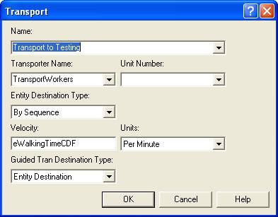
Figure 7.19: TRANSPORT module
Figure 7.19 shows the TRANSPORT module for the test and repair example. The TRANSPORT module is very similar to the ROUTE module, except the user specifies the transporter to use by name (and/or unit number). In most cases, this will be the same transporter as allocated in the REQUEST module. Then, the user can specify the type of destination (By Sequence, attribute, station, or expression). In this case, the By Sequence option should be used. In addition, the velocity of the transport can be specified. The Guided Tran Destination Type field allows the user to send the transporter to a location different than that specified by the entity’s destination. This is useful in guided path transporters to send the transporter through specific intersections on its way to the final destination. This option will not be used in this text.
After making these changes, you can run the model with the default animation and find out how the system operates with the transporters. Recall that in Figure 7.15 that there was a little check box to indicate whether or not to collect statistics on the transporter. If this is checked, and the Transporters check-box is checked on the Project Parameters tab on the Run Setup dialog, then the number busy and utilization of the transporters will be reported automatically.
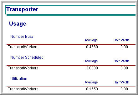
Figure 7.20: Transporter statistics
As can be seen in Figure 7.20, the utilization of the three transporters is very low. Less than three workers a probably need for the transport task. The reader is asked to explore this issue an exercise.
7.2.2 Animating Transporters
A significant advantage of using transporters in this situation rather than resource constrained transfer is the animation that is available with transporters. This section converts the previous animation so that it uses transporters. The basic steps in converting the model are as follows:
Cut and paste the animation from the file, RepairShopResourceConstrainedTransferWithAnimation.doe, to the file RepairShopWithTransportersNoAnimation.doe and rename it.
Select and delete each route connector and station marker from the previous animation.
Delete each animation queue from the flow chart modules. Redefine each animation queue with the appropriate name within the copied animation.
Use the Add Distance button on the Animate Transfer toolbar to place station markers and distance connectors for every from/to combination within the distance set as shown in Figure 7.21. For every station marker, make sure that the "Parking" check-box is checked. This will indicate that the transporter will be shown at that station when it is idle (parked).
Add a variable animation to show the current number of busy transporters. This can be easily done using the expression builder to find the transporter variables (
NT(TransportWorkers)). To learn more about the variables associated with transporters look up "Transporter Variables" within Arena’s help system.Use the transporter button in the Animate Transfer toolbar to define a transporter picture. The process is essentially the same as that for defining a resource animation picture as shown in Figure 7.22.
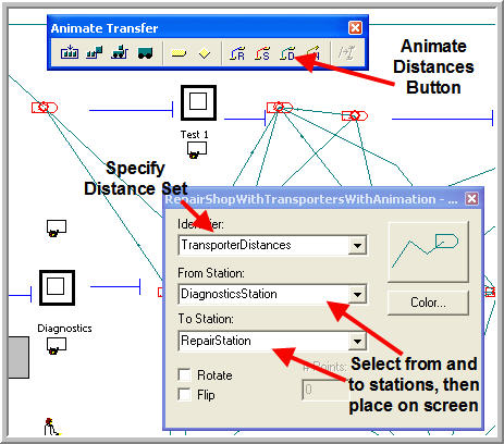
Figure 7.21: Placing the distance animation elements
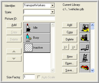
Figure 7.22: Defining the transporter picture
Now the animation involving the transporters is complete. If you run the model with animation turned on, you will see that there is only about 1 unit of the transporter busy at any time. Also, you will see that the idle transporters become parked after their transport when no other transport requests are pending. They will remain at the station where they last dropped off a part until a new transport request comes in. In the animation, a picture was used that showed a person sitting for idle and walking/carrying something to show busy. Another way to show that the transporter is carrying something is to enable the ride point for the transporter. To place a ride point in the busy transporter picture, select the Ride Point option from the Object menu after double-clicking on the busy picture in the transporter animation dialog. If no ride point is defined, the entity picture will not appear.
In this model, the worker stays at the location where they drop off the part if no part requires transport. Instead, the worker could go to a common staging area (e.g. in the middle of the shop) to wait for the next transport request. The trick to accomplishing this is to not use the ENTER module. The basic idea would be implemented as follows:
STATION
DECIDE
    IF requests are waiting
        FREE the transporter
        continue normal station processing
    ELSE
        SEPARATE 1 duplicate into station
        MOVE to staging area
        FREE the transporter
    ENDIF
END DECIDE
Notice that in the case of no waiting requests, a duplicate of the entity is used to continue the control of the transporter to move it to the staging area. The reader is asked to implement this idea as an extension to this problem in the exercises. The notion of having an entity control or "drive" the transporter around is very useful in modeling systems that have complicated transporter allocation rules or systems that naturally have a driver, e.g. bus systems.
A distance module allows the physical transport aspects of systems to be modeled. An important aspect of this type of modeling is the movement of entities through space. The conveyor constructs allow for a finer representation of the usage of space between stations. That topic is taken up in the next section.